Operational Specifications 10
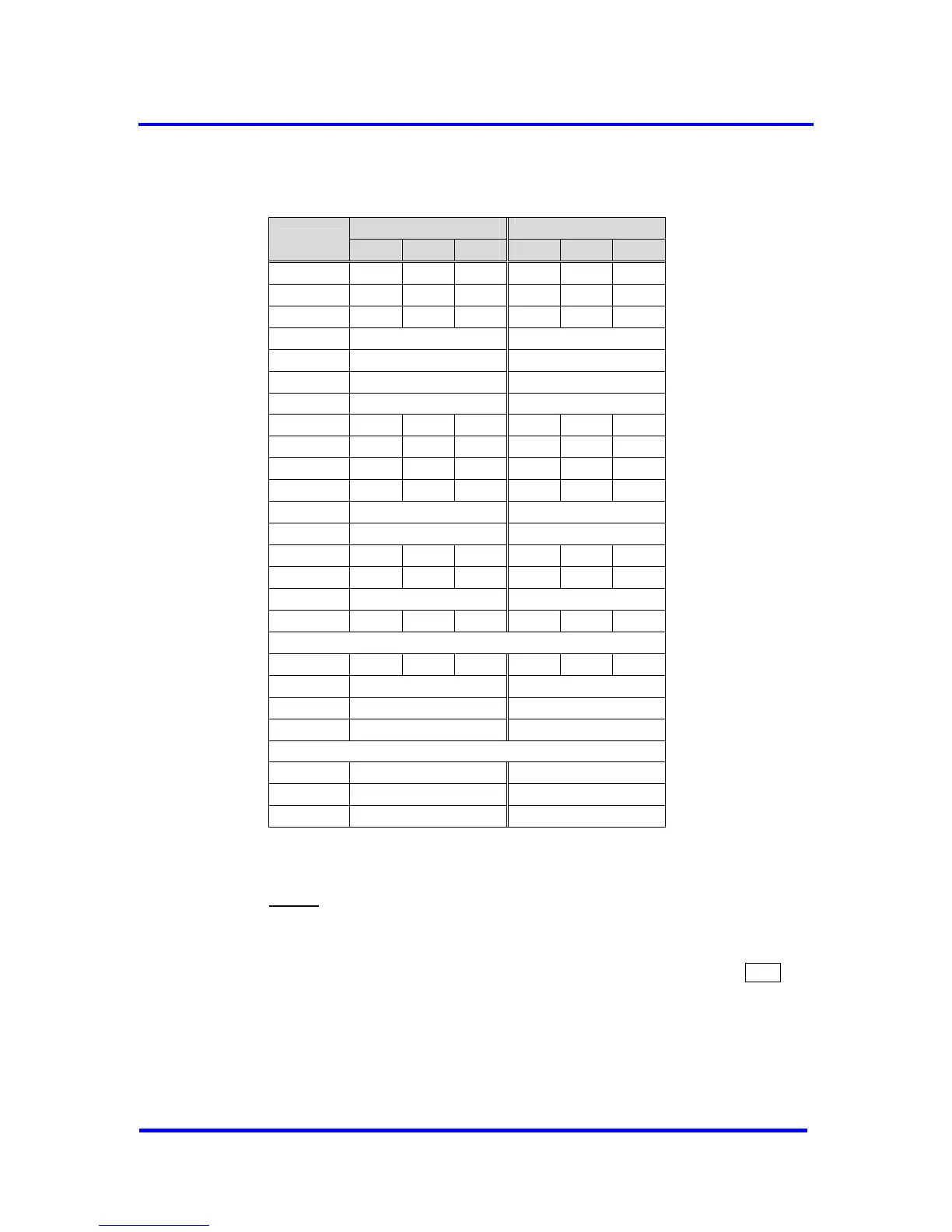
MILLIMETER INCH
SYMBOL
MIN NOM MAX MIN NOM MAX
A ─── ─── 2.45 ─── ─── 0.096
A1 0.15 0.25 0.35 0.006 0.010 0.014
A2 1.95 2.05 2.10 0.077 0.081 0.083
D 13.90 BASIC 0.547 BASIC
D1 10.00 BASIC 0.394 BASIC
E 13.90 BASIC 0.547 BASIC
E1 10.00 BASIC 0.394 BASIC
R2 0.13 ─── 0.30 0.005 ─── 0.012
R1 0.13 ─── ─── 0.005 ─── ───
Θ 0° 3.5° 7° 0° 3.5° 7°
Θ1 0° ─── ─── 0° ─── ───
Θ2 10° REF 10° REF
Θ3 7° REF 7° REF
c 0.11 0.15 0.23 0.004 0.006 0.009
L 0.73 0.88 1.03 0.029 0.035 0.041
L1 1.95 REF 0.077 REF
S 0.40 ─── ─── 0.016 ─── ───
b 0.22 0.30 0.38 0.009 0.012 0.015
e 0.80 BSC. 0.031 BSC.
D2 8.0 0.315
E2 8.0 0.315
Tolerances of Form and Position
aaa 0.25 0.010
bbb 0.20 0.008
ccc 0.20 0.008
Figure 10-22 : Package Dimensions and Tolerances
Notes:
1. Dimensions D1 and E1 do not include mold protrusion. Allowable
protrusion is 0.25 mm per side. Dimensions D1 and E1 do not
include mold mismatch and are determined at datum plane ─H─.
2. Dimension b does not include dambar protrusion. Allowable dambar
protrusion shall be 0.08 mm total in excess of the b dimension at
maximum material condition. Dambar cannot be located on the
lower radius of the lead foot.
VPC3+C User Manual
Revision 1.03 95
Copyright © profichip GmbH 2004-2006