5 Overview of equipment and control elements
5.1
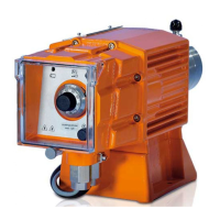
Overview of equipment
Fig. 3: Overview of equipment, complete
1 Control unit
2 Drive unit
3 Liquid end
1
2
3
4
5
6
7
1
2
3
4
5
6
7
8
2
3
1
6
7
A.
B.
C.
P_G_0053_SW
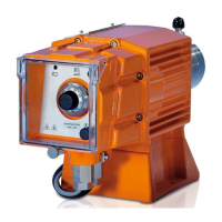
Fig. 4: A. Liquid end with PV bleed valve; B. Liquid end with NP bleed valve; C. Self-bleeding liquid end
(SEK)
1 Discharge valve
2 Backplate
3 Dosing head
4 Bleed valve
5 Bypass hose sleeve
6 Diaphragm rupture indicator (optional)
7 Suction valve
8 Bleed valve, self-bleeding
Self-bleeding liquid ends (SER)
Externally self-bleeding liquid ends with groove
(SER) look identical to liquid ends with bleed valve.
The SER valve is only approved up to a pressure
of 10 bar. We recommend operating a pump with a
SER valve of between 1 ... 7 bar.
Overview of equipment and control elements
17
DosingPump.ir

 Loading...