Chapter 2 Hardware Configuration
Page: 2-26
Prox-1635LF USER
′
S MANUAL
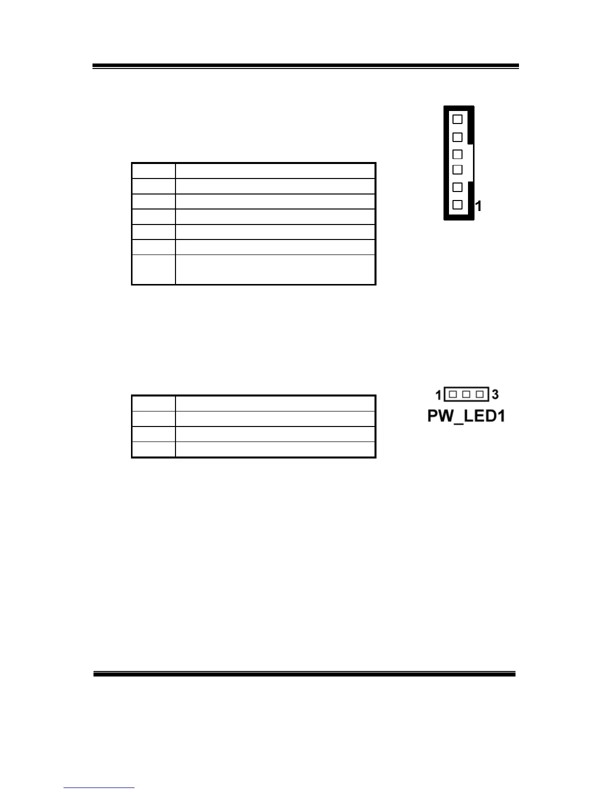
2-32. INVERTER CONNECTOR
JP15 : Inverter Connector
The pin assignment is as follows:
PIN ASSIGNMENT
1 +12V
2 +12V
3 GND
4 VCC
5 GND
6 ENABKL (Inverter backlight
ON/OFF control signal)
2-33. POWER LED CONNECTOR
PW_LED1 : Power LED Connector
The pin assignment is as follows:
PIN ASSIGNMENT
1 PW_LED+
2 PW_LED+
3 PW_LED-
JP15