93-530-70 Issue 0 Page 17 of 44 © Protec Fire Detection PLC 2007
12.2 Installing and Connecting The Standby Batteries
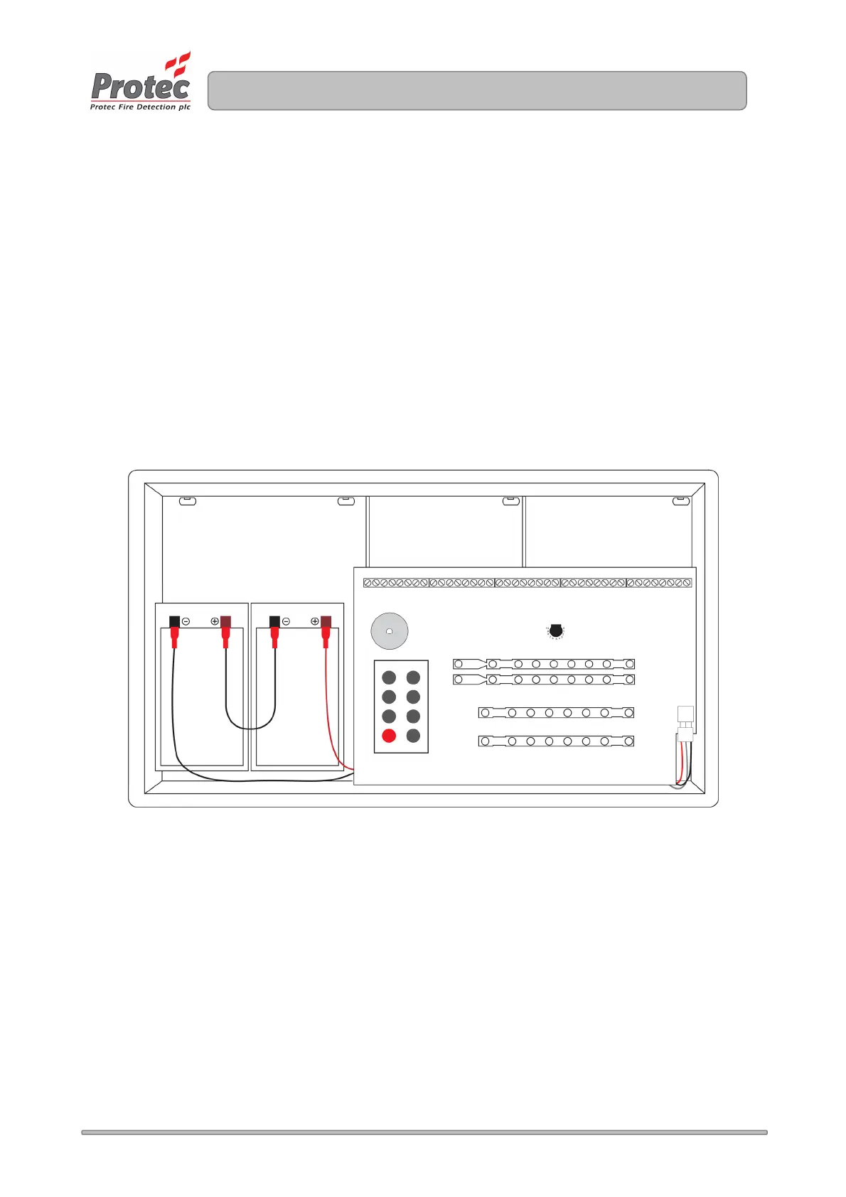
The panel is designed to house two 12V 3.3Ah Valve Regulated Sealed Lead Acid (SLA) batteries.
These fit into the left hand compartment of the 3300 and should be secured with the Tie Wraps
provided.
The two batteries must be connected in series, a connecting link is supplied for this purpose.
The batteries must then be connected to the Power Supply PCB using the wires provided, please
observe polarity when connecting.
Ensure all spade connectors are pushed fully home onto the battery terminals.
Figure 12.1 shows the location and connection details for the batteries.
Figure 12.1 Installation of 3300 Standby batteries (shown with 3300 lid removed)
12.3 Switching On
Switch the fused isolator to the ‘ON’ position. The ‘Supply Present’ indicator should illuminate on the
front of the panel and, assuming all other connections are correct and the end of line units are present
(and the correct value) , no other faults should be displayed.
The 3300 is now ready to be programmed.
www.acornfiresecurity.com
www.acornfiresecurity.com