93-530-70 Issue 0 Page 43 of 44 © Protec Fire Detection PLC 2007
33.0 Appendix 4. 3300 Main PCB Details
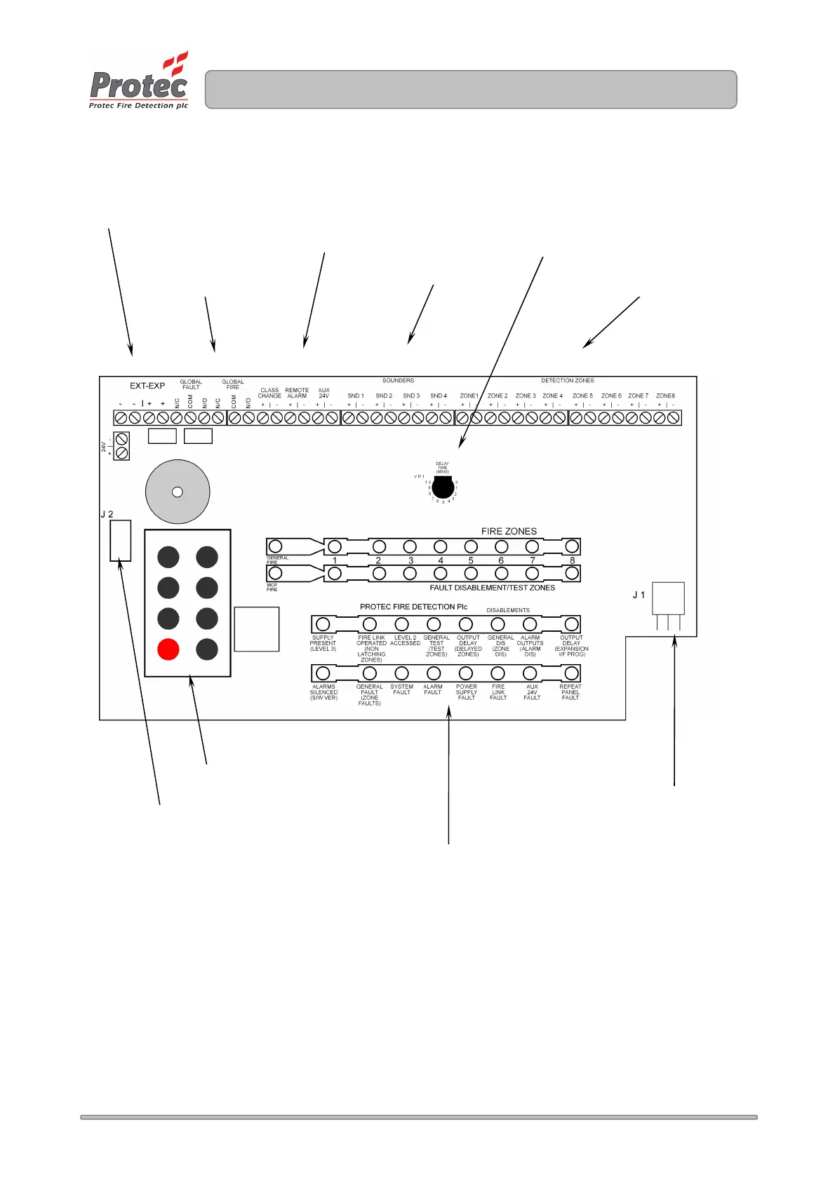
The diagram below shows the 3300 control PCB and highlights the main connections and controls.
24V dc
Power
Connector
Keypad
Detector Zone Connections
Sounder Connections
Internal
Expansion
Interface
Connector
Auxiliary Connections
LED Display
Delay Time Setting Control
Clean Contact Outputs
Repeat Panel Connections
www.acornfiresecurity.com
www.acornfiresecurity.com