93-530-70 Issue 0 Page 26 of 44 © Protec Fire Detection PLC 2007
14.7 Programming Expansion Interface Node Information
The 3300 can accept interfaces on its expansion ports. The 3300 must be programmed with the
number of nodes to expect on its expansion ports, both internal and external.
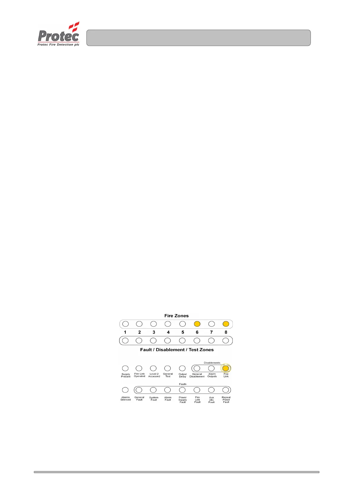
The number of nodes is expressed in binary, using a 5 bit code. Please note that the 3 remaining bits
(indicated on zones 1, 2 and 3) are reserved for future features and should be left clear.
The procedure for programming expansion information is as follows:
1. From access level 1 enter the 5 digit engineer code 1 3 4 2 4. The ‘Supply Present’ indicator
will flash indicating level 3 has been accessed and all programming features are available.
2. Scroll to the ‘Fire link’ indicator (within the disablements section) by repeatedly pressing button 2.
Any node information currently programmed will be displayed on row 1 of the display. Accept the
option by pressing button 3.
3. The ‘Fire Link ’ indicator will flash to indicate this option has been accepted.
4. Using button 2 and button 1 enter the number of system nodes present in a binary format. The
zone 8 indicator is the least significant bit of the number and the zone 4 indicator is the most
significant bit.
Please consult Appendix 3 for clarification of decimal to binary conversion.
Note: The number of nodes must include all nodes on the external expansion port and any nodes
on the internal expansion port. For example if the 3300 has two repeat panels on its external
expansion port and one fire link Interface on its internal expansion port the total number of nodes
entered would be three.
5. Press button 3 to return to the selection menu.
6. Press button 4 to accept and program the expansion set-up and return to access level 2.
Figure 14.1 Example of programming 5 nodes into the 3300.
www.acornfiresecurity.com
www.acornfiresecurity.com