93-530-70 Issue 0 Page 11 of 44 © Protec Fire Detection PLC 2007
6.0 Testing of Cabling Prior to Connection
Before connecting any external cables to any field device (detectors, sounders, auxiliary inputs or
outputs), or the 3300, tests must be carried out using a 500V dc insulation tester (Megger
TM
). The
readings between each cable core, and each core and earth should be greater than 10MΩ.
Important Notes:
• Equipment connected to the cabling during insulation tests could be damaged with the high
voltages used during the test.
• Field devices and the 3300 MUST NOT be connected when high voltage insulation tests are being
performed on the cabling, the cabling must be completely discharged prior to connection to any
field devices or the 3300.
7.0 Detector Circuit Connections
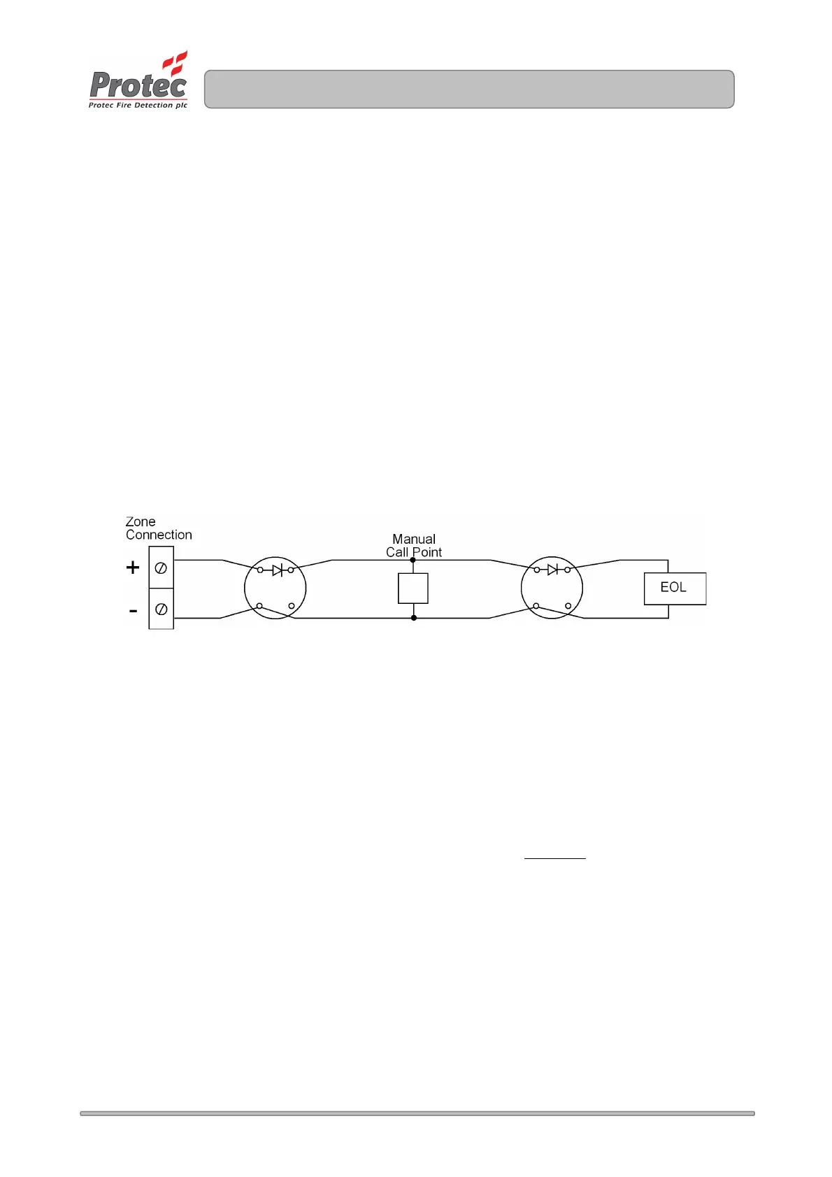
Figure 7.0 shows a typical connection regime for a detector zone on the 3300.
Figure 7.0 Typical 3300 Detector Connection
• Ensure the length of the zone wiring is no more than 500 metres.
• Ensure the resistance of each conductor is no more than 15Ω.
• Ensure the capacitance of the zone wiring is no more than 0.27µF (micro-Farads)
when no end of line capacitor is present.
• The end of line unit (8k2 resistor or 100µF/22Ω network) must be placed at the very end of the
detector zone wiring, ensuring the whole zone is monitored.
• Spurs should not be connected from the zone wiring as the spur will not be
monitored for open
circuit faults.
• To ensure compliance with EN54 Part 2 each detector base must include a series low voltage
drop diode, such that manual call points following a removed detector still function correctly.
Protec S3000 bases incorporate the diode as standard.
• Manual call points must incorporate a series resistor to ensure the zone does not enter a short
circuit fault condition when the manual call point is activated. If the panel is to be able to
distinguish between automatic and manual zone activations the resistor value in the manual call
point must be 180Ω. In retrofit situations, values up to 560Ω can be used but ‘MCP fire’ may not
be given in all instances.
Protec 3300 manual call points incorporate the series 180Ω resistor as standard.
www.acornfiresecurity.com
www.acornfiresecurity.com