93-530-70 Issue 0 Page 10 of 44 © Protec Fire Detection PLC 2007
5) Preparing and Fixing the Panel Back-box
The mains cable entry position should be kept away from other system cabling.
Carefully knock out the required cable entry positions and mount the enclosure at the position
prepared in (2) whilst feeding the cables into the enclosure.
6) Refitting the Main PCB
Note: Before re-fitting the main PCB the mains power connections to the Power Supply
PCB should be connected. See section 12.0.
DO NOT SWITCH MAINS POWER ON AT THIS POINT !!
Route the battery cables through to the battery compartment using the channels provided.
Replace the Main PCB (a reversal of removal), ensuring it is pushed fully down to the bottom
edge of the panel. Secure with the two screws removed previously. Take care not to over
tighten the screws.
Re-connect the three way cable from the Power Supply to the Main PCB, do not use undue
pressure and ensure the cable is clipped into the locking ramp on the PCB header securely.
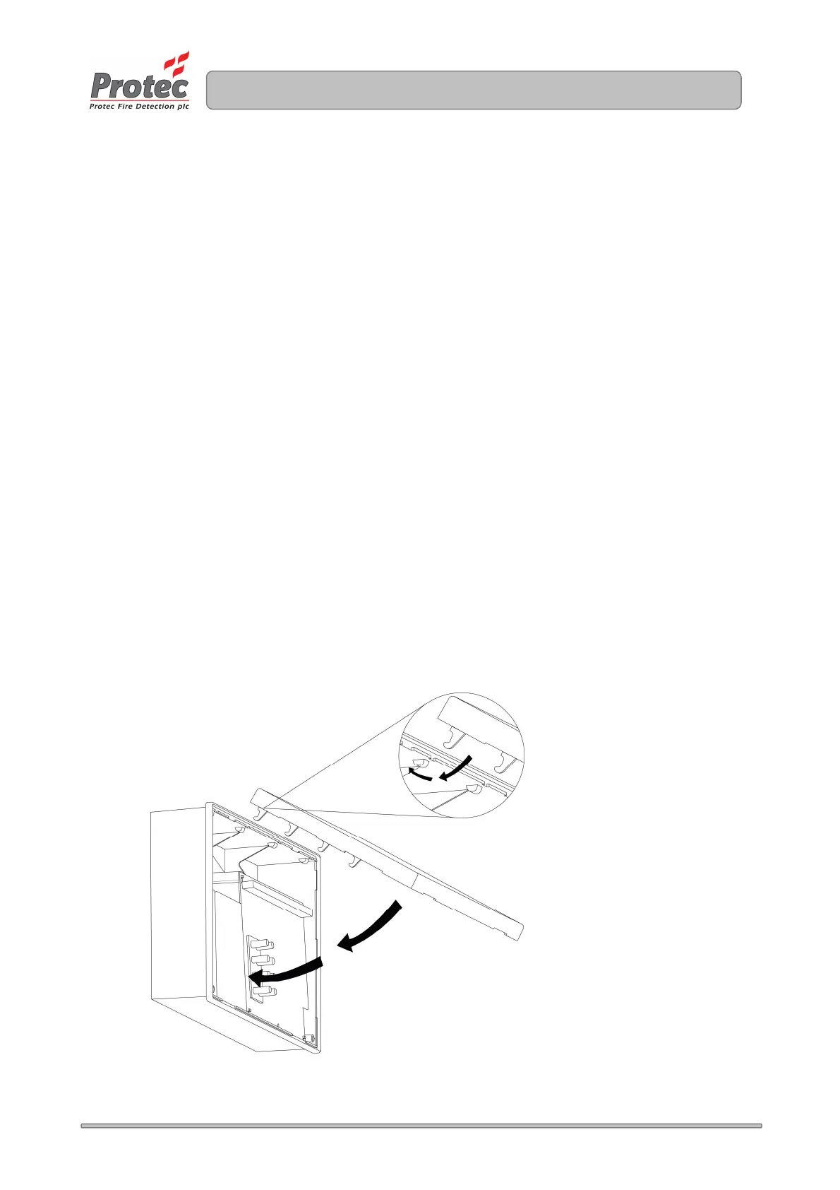
7) Re-fitting the Door
Replace the plastic door by offering the top of the door up to the groove at the top of the
plastic back-box.
Swing the door down and ensure it pushes fully home into the back-box, without fouling the
rubber keypad or light-guides on the main PCB. See figure 5.3 for details.
Tighten the two screws in the lower two corners of the door, and replace the screw covers.
Figure 5.3 – Refitting the 3300 Door.
www.acornfiresecurity.com
www.acornfiresecurity.com