93-530-70 Issue 0 Page 9 of 44 © Protec Fire Detection PLC 2007
4) Removal of the Main PCB.
NOTES ON ANTI-STATIC HANDLING OF THE PCBs
Before handling any of the circuit boards in the 3300 it is vital that any operatives
discharge themselves of any static charge that may have built up on them. This can be
done by momentarily touching a solid earth point (a non-painted part of a radiator, for
example).
Handle the PCBs by their sides and DO NOT touch the electronic components on them.
The PCB should be stored in a clean, dry place away from the place of work. Retain the
PCBs in a cardboard box for safety until they are required.
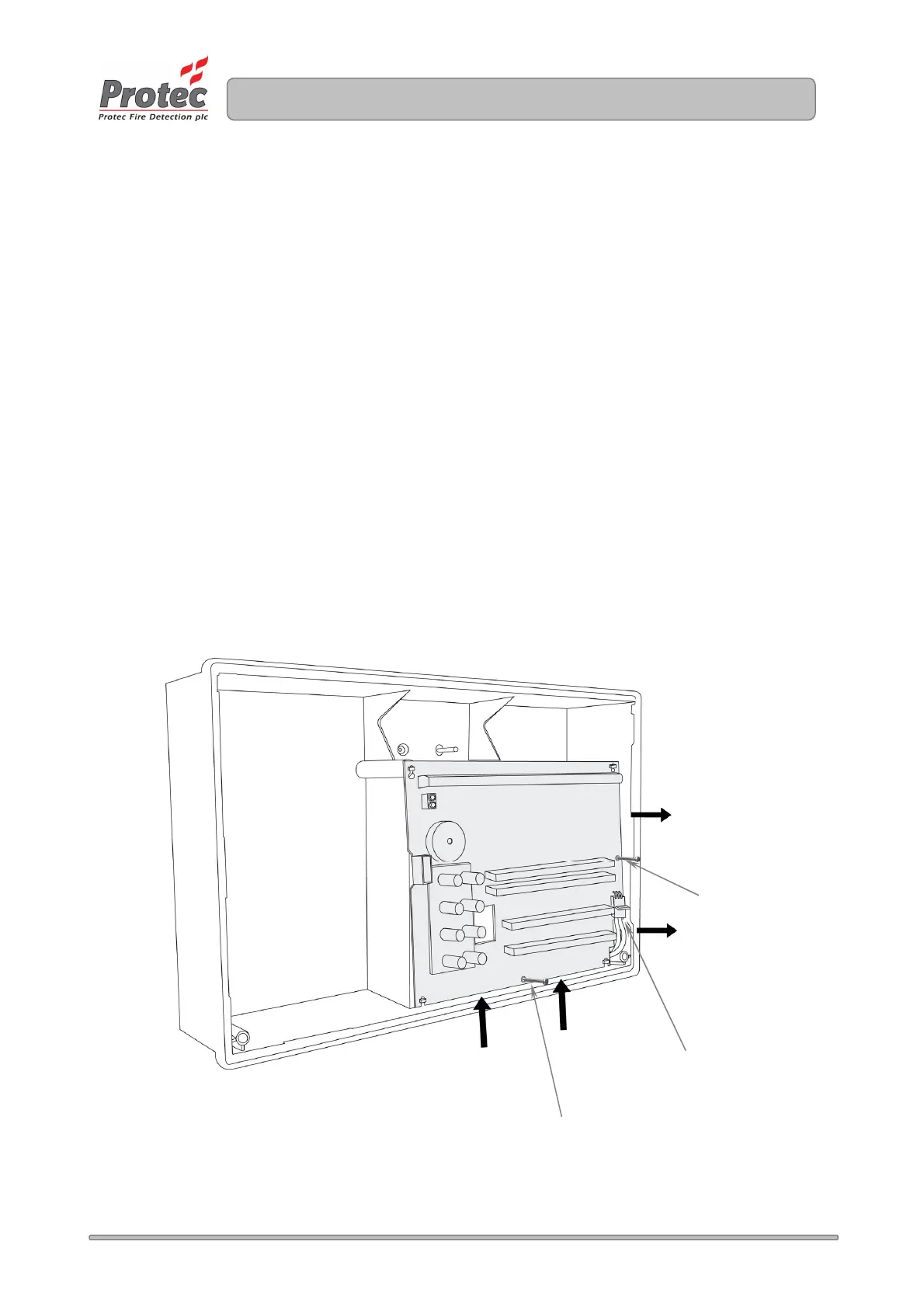
Disconnect the 3 way connector from the main PCB, taking care not to strain the connector or
the PCB. Leave the connector attached to the Power Supply PCB.
Unscrew and remove the two mounting screws on the main PCB. Carefully slide the Main
PCB upward (stage 1) and lift away from the plastic enclosure (stage 2). See figure 5.1.
Store all screws and PCBs in a safe, dry place.
Figure 5.1 – Removal of the 3300 Main PCB.
.
PCB fixing screw
Stage 1
Stage 2
3 way power
connector
PCB fixing screw
www.acornfiresecurity.com
www.acornfiresecurity.com