Pulsar® Precision Operaon and Installaon Manual (Model PS-1HCE) Rev 2.0 04/2022
11
5 InstallaonInstrucons
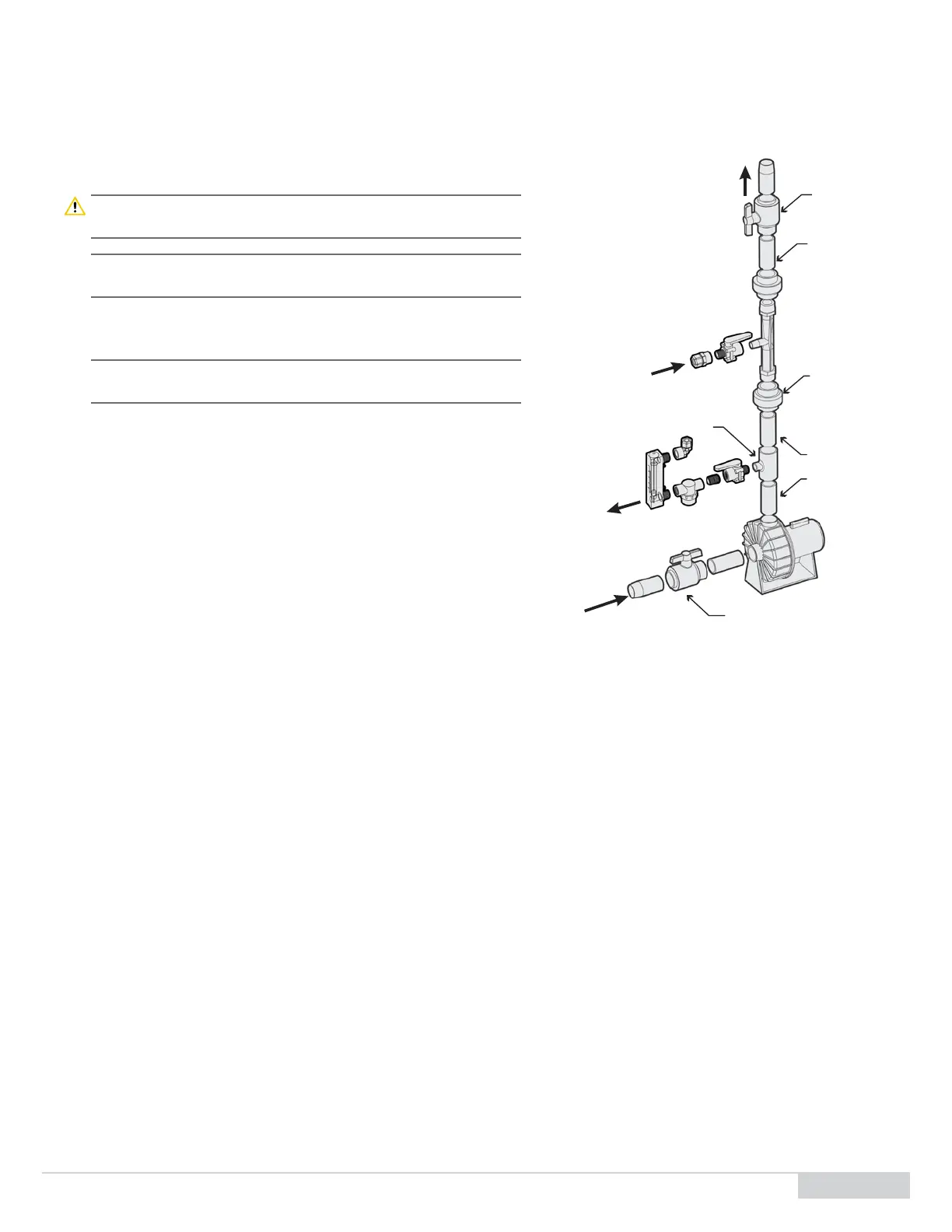
5.1 Install the Booster Pump - Venturi Loop
Downstream of your pool lter(s), connect the booster pump sucon and
venturi outlet 1 ½" piping: See Figure 4.
Cauon: Shut o the pool pump and isolate the pool return piping locaon
used for the installaon to prevent excessive water leakage.
Note: Refer to the Figure 1 on page 6 for proper locaon of system
piping connecons.
1. Drill and tap two 1 ½" NPT holes that will be used for the booster
pump inlet and venturi outlet, respecvely.
Note: Saddle clamps or tee’s can be used as an alternave for a cleaner
installaon.
2. Since not all pipes run full, for horizontal pipe, drill the holes on the
side or boom.
3. Cut the 12" x 1 ½" PVC threaded nipple provided in the installaon kit
in half.
4. Apply plumber's tape to the threads of the two nipples and thread the
nipples into the 1 ½" tapped holes.
5. Add silicon seal bead around the thread connecon to help make a
waterproof seal.
6. Take the 1 ½" ball valves and glue them onto the 1 ½" nipples. These
are the isolaon valves to the inlet and outlet of the booster pump
and venturi.
7. Glue the 2” x 1 ½" reducer bushings to the pump union tailpieces and
connect to the booster pump sucon and discharge.
8. Apply plumber's tape to the venturi threads and thread the 1 ½" unions to both ends of the venturi.
9. Thread the 3/4" x 1/2" reducer coupling onto the venturi sucon.
10. Complete the 1 ½" piping run from the inlet nipple to the booster pump sucon.
11. Connect the discharge of the booster pump with the 1 ½" to 1/2" reducer bushing and the 1 ½" venturi ensuring the venturi is oriented in
the direcon of ow.
12. Complete the 1 ½" piping run from the outlet of the venturi to the outlet nipple on the pool return using as few 90° elbows as praccable.
The use of 45° elbows in place of 90° elbows are preferred to minimize backpressure on the venturi outlet.
Figure4. Complete the 1 ½" piping run
cut 1-1/2" PVC pipe
(installer provides)
1-1/2" thread x slip
PVC union
cut 1-1/2" PVC pipe
(installer provides)
1-1/2" Slip
PVC Ball Valve
(installer provides)
flow to
feeder
flow from
feeder
flow to
pool
1-1/2" slip x 1/2" FNPT TEE
(installer provides)
1-1/2" Slip PVC Ball Valve
(installer provides)
flow
from
pool