Pulsar® Precision Operaon and Installaon Manual (Model PS-1HCE) Rev 2.0 04/2022
13
5.6 Wire the Booster Pump to the Control Box
Using a cered electrician, connect the booster pump to the control box using 12 AWG
or bigger wire.
Warning:Risk of dangerous or fatal electrical shock. Be sure that power to the motor
circuit is o before working on wiring, wiring connecons, or the motor. Re-
install the motor end cover and all other wiring covers before turning on the
power.
Note: The pump must be permanently connected to the control box. Be sure no other
lights or equipment are on the same circuit.
Note: Be sure no other lights or equipment are on the same circuit as the control box.
Note: Use Ground Fault Circuit Interrupter (GFCI) as a master on-o switch.
1. Refer to Appendix secon 10.2.1 and 10.2.2 for control box wiring help.
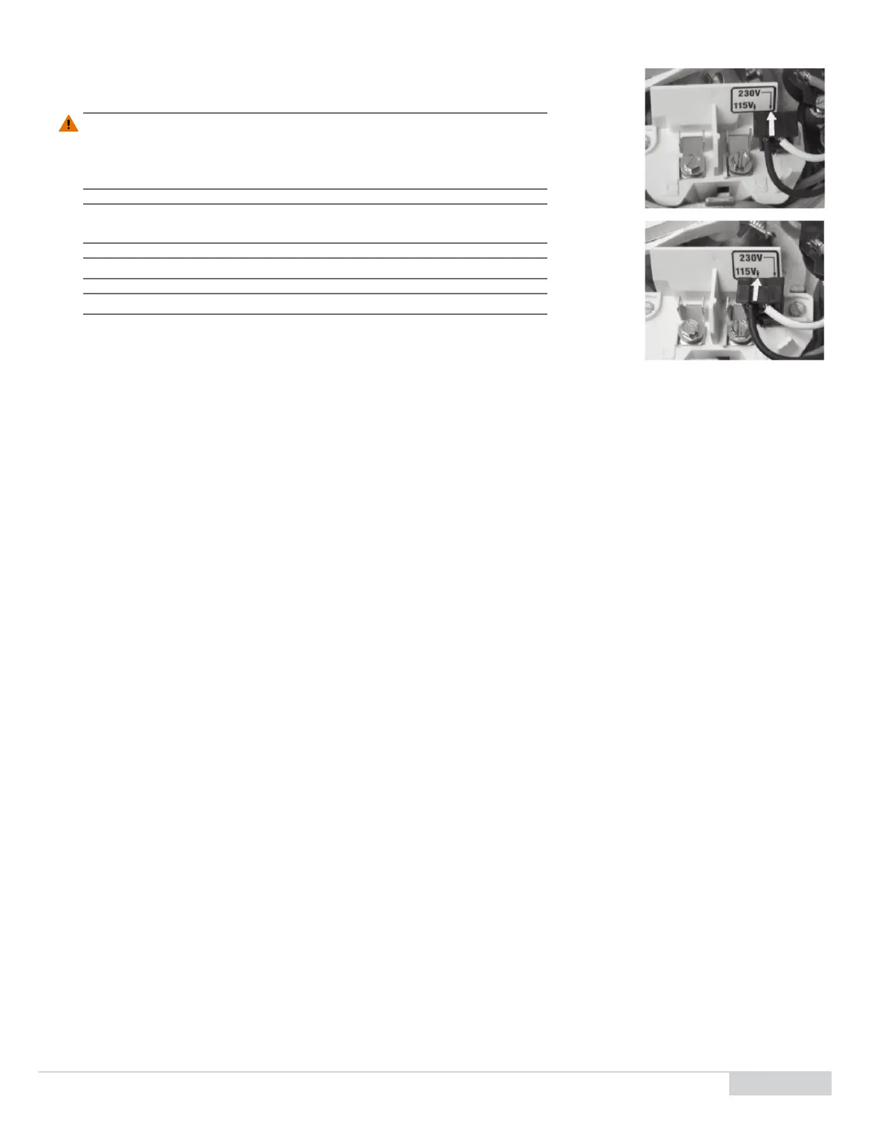
2. Remove the booster pump motor end cover to expose the pumps dual-voltage
selector, Figure 8.
3. If you have 230 V motor supply voltage, conrm that the plug is set for 230 V. The
arrow on the plug will point to the 230 V posion, which is the default posion of the pump (the plug only connects with one prong in this
posion).
4. If you have 115 V supply, pull the plug straight up and place it on the two brass prongs so that the arrow points to the 115 V posion.
5. Open the control box cover and wire the booster pump to the control box using the wiring diagram, Figure 13.
6. Replace the booster pump motor end cover to complete the booster pump wiring.
5.7 Connect the Flow Switch Cable
Connect the orange ow switch cable to the ow switch:
1. Route the ow switch cable so that it is not a tripping hazard.
2. The M12 connector on the cable goes in one direcon. Screw in the connector so that it fully engages with the ow switch.
5.8 Prime the System
1. Allow pool water to enter the 1 ½" and 1/2" piping and tubing to conrm overall water ghtness.
2. Open the 1 ½" inlet ball valve and allow water to enter the booster pump checking for leaks.
3. Slowly crack open the booster pump discharge union, allowing water to ow out conrming that the booster pump is fully primed.
4. Reconnect and ghten the discharge union.
5. Open the 1 ½" outlet ball valve fully priming the enre booster pump / venturi loop.
6. Open the 1/2" gray inlet and outlet feeder ball valves, allowing water to reach the feeder.
7. Check for leaks at the booster pump and venturi loop and feeder and ow switch. Redo any leaking connecons.
5.9 Connect the Control Box to the Feeder
1. Connect the feeder control cable on the control box (second from the le) to the main cable coming out of the back of the feeder hopper.
2. Orient the notch of both connectors so they can be pushed in together. The 4 pin connectors from the control box and the feeder are keyed
so they t together in only one orientaon.
3. Once mated, turn the locking ring clockwise unl hand ght. (The connectors are sealed to IP68 when mated correctly.)
Figure8. Dual-Voltage Selector