Pulsar® Precision Operaon and Installaon Manual (Model PS-1HCE) Rev 2.0 04/2022
15
6.1.2 ControlBoxPreparaon
Danger: Ensure the control box is not plugged into power prior to removing the top cover,
adjusng DIP switches, and wiring in the booster pump. Failure to do so may result in
death or serious injury from electrical shock.
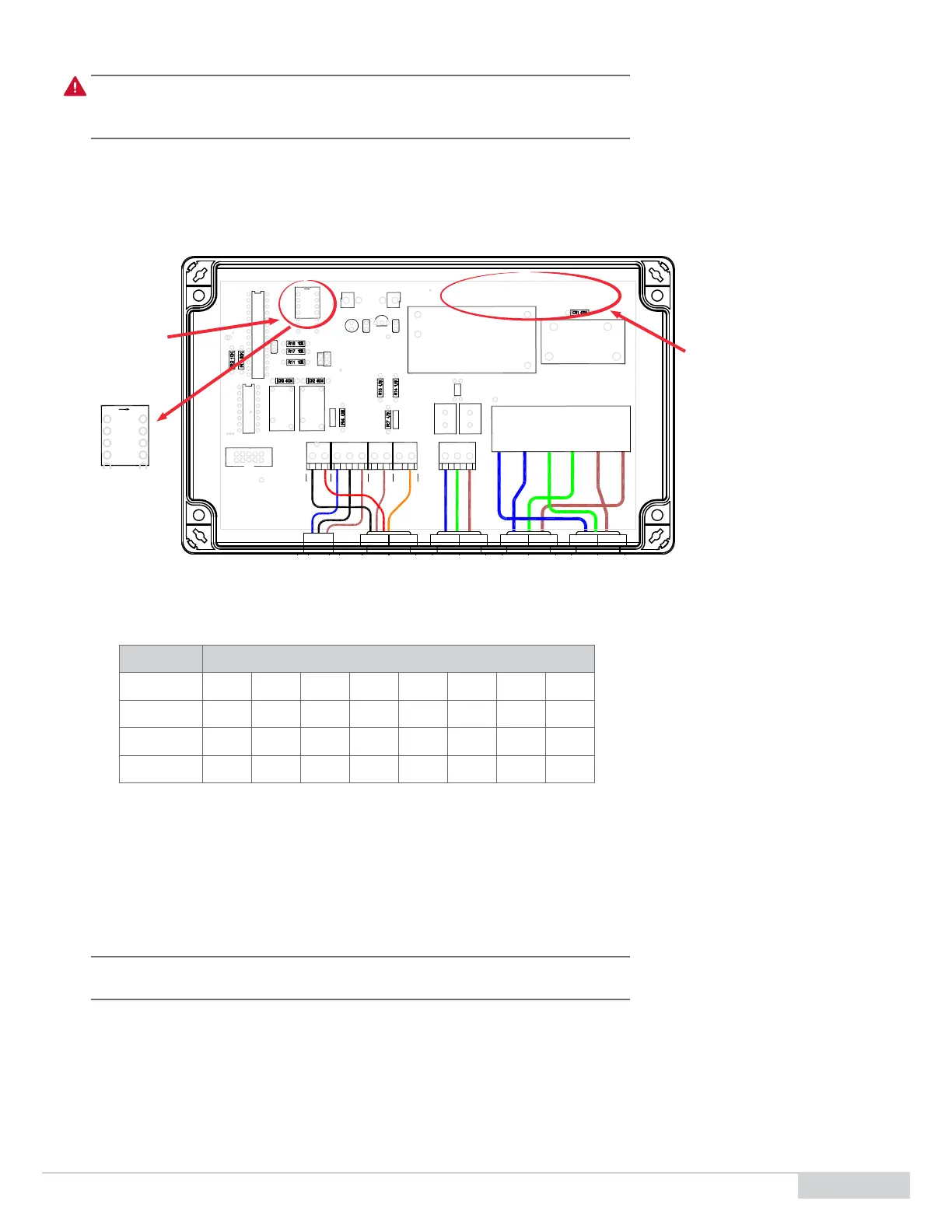
1. Prior to powering up the control box, verify the output seng and economy mode by removing the top cover and idenfying the DIP
switch sengs in accordance with the Feed Cycle Sengs table in step 4, below.
2. The DIP switches are located near the top le of the controller and the feed cycle sengs are on the top right. See Figure 9, below.
3. There are 4 DIP switches. Switches 1, 2, 3 control the feed solenoid On/O me and switch 4 turns the economy mode On/O.
AC POWER CORD
14/3 10' SJTW EU COLOR CODE
PROVIDED BY MELLC
PROVIDED BY IWC
FLOW SWITCH JACK
PROVIDED BY MELLC
18/7 20' CABLE UL CSA CE SJTWO
LEVEL SWT
KEY
1
COM
12
HD1
TB8
HI LIMIT SWT
FLOW SWITCH
+24 VDC
3
COM
FEED SOL
1
-24 VDC
1
2
TB7
TB6
COM
COM
WASH SOL
TB4 TB3
SW1
ON
C4
104
PIC16F883
2003
OJE-124
U4
RY3
U1
107
104104
RY2
OJE-124
R10
470
TEST OFF
HD2
1
4
3
2
C1
CLP1
C2
U2
LM2950
1 AMP
FU1
C3
CLP2
120/240 VAC
ORP IN
COM
1
GND
HOT
23
TB2
LINE IN NEUTRAL
PUMP COM
1
TB1
2
LINE IN 120/240 VAC
LINE GND
PUMP GND
3 4
PUMP HOT
65
22/38
FEED CYCLES
ON
OFF
ON
+
PS1
MPM-20-24
10K10K
R6
R5
FOD81 4
1
N
DIP SWITCH
ECONO MODE
ON
-
O F FS W 4
SW3
SW2
SW1
11/49 16/446/54
ON
OFF
OFF
OFF
OFF
OFF
L
OFF
OFF
ON
ON/OFF
RY1
G4A
32/28
38/22
27/33
ON
OFF
OFF
ON
ON
OFF
ON
OFF
ON
44/16
ON
ON
ON
3 210
To 115-430-03 Feeder Terninal Block Wiring Asembly
INLINE CONNECTOR
BLA CK WIRE 0 COMMON
RED WIRE 2 FEED DIN +
ORANGE WIRE 3 WATER DIN +
BROWN WIRE 1 HI LIMT SW
WIRE LEGEND:
Figure9. DIP Switch Locaon and Feed Cycle Sengs
4. The below Feed Cycle Sengs table shows On/O feed mes in seconds based on the combinaon of DIP switch sengs. The higher on
mes yield higher chlorine output.
ON/OFF FEEDCYCLES
DIPSWITCH 6/54 11/49 16/44 22/38 27/33 32/28 38/22 44/16
SW1 OFF ON OFF ON OFF ON OFF ON
SW2 OFF OFF ON ON OFF OFF ON ON
SW3 OFF OFF OFF OFF ON ON ON ON
5. Set your desired output and economy mode seng in accordance with the above Feed Cycle Sengs table.
a. For example, SW1 on, SW2 o, SW3 on yields 32 sec On and 28 sec O for the feed solenoid – Approximately 75% chlorine output of
the feeder.
b. If SW4 is o, the booster pump will be always on. If SW4 is on, the booster pump will run in economy mode and stop 20 sec aer the
last feed or wash cycle (or 5 min if the pump just started up).
c. The DIP switches can be toggled at any me with the controller powered o.
Note: If using an ORP or chemical controller for dosing, start with the dip switches congured
to the highest output. This is SW1, SW2, and SW3 on.
6. Close the top cover of the controller to resume start up.
DIP Switch
Feed Cycle Sengs
AC POWER CORD
14/3 10' SJTW EU COLOR CODE
PROVIDED BY MELLC
PROVIDED BY IWC
FLOW SWITCH JACK
PROVIDED BY MELLC
18/7 20' CABLE UL CSA CE SJTWO
LEVEL SWT
KEY
1
COM
12
HD1
TB8
HI LIMIT SWT
FLOW SWITCH
+24 VDC
3
COM
FEED SOL
1
-24 VDC
1
2
TB7
TB6
COM
COM
WASH SOL
TB4 TB3
SW1
ON
C4
104
PIC16F883
2003
OJE-124
U4
RY3
U1
107
104104
RY2
OJE-124
R10
470
TEST OFF
HD2
1
4
3
2
C1
CLP1
C2
U2
LM2950
1 AMP
FU1
C3
CLP2
120/240 VAC
ORP IN
COM
1
GND
HOT
23
TB2
LINE IN NEUTRAL
PUMP COM
1
TB1
2
LINE IN 120/240 VAC
LINE GND
PUMP GND
3 4
PUMP HOT
65
22/38
FEED CYCLES
ON
OFF
ON
+
PS1
MPM-20-24
10K10K
R6
R5
FOD 814
1
N
DIP SWITCH
ECONO MODE
ON
-
O F FS W 4
SW3
SW2
SW1
11/49 16/446/54
ON
OFF
OFF
OFF
OFF
OFF
L
OFF
OFF
ON
ON/OFF
RY1
G4A
32/28
38/22
27/33
ON
OFF
OFF
ON
ON
OFF
ON
OFF
ON
44/16
ON
ON
ON
PUMP OUT
3 2 10
To 115-430-03 Feeder Terninal Block Wiring Asembly
INLINE CONNECTOR
BLACK WIRE 0 COMMON
RED WIRE 2 FEED DIN +
ORANGE WIRE 3 WATER DIN +
BROWN WIRE 1 HI LIMT SW
WIRE LEGEND: