Pulsar® Precision Operaon and Installaon Manual (Model PS-1HCE) Rev 2.0 04/2022
9
4 Pre-installaonInstrucons
4.1 Prepare the Site
Before installing equipment, ensure that:
1. The site has all electrical connecons installed. All electrical lines should be secured to meet site safety procedures and to prevent tripping
over electrical lines.
Danger: All wiring connecons, fusing, grounding, inspecon, and maintenance of wiring
must be performed by a licensed electrician in accordance with the Naonal Electric
Code (NEC), Occupaonal Safety and Health Act (OSHA) in the United States, and all
local electrical codes. Failure to properly install and wire this product can result in
property damage, injury, or death, and may aect warranty coverage.
2. Site meets criteria noted in Site Requirements on page 9.
4.1.1 SiteRequirements
The feeder must t in the selected room with enough clearance for maneuvering and servicing the equipment.
– Recommended clearance for feeder installaon is 48" L x 48" W x 76" H [121.9 cm x 121.9 cm x 193.0 cm]
– Minimum clearance for feeder installaon is 36" L x 36" W x 64" H [91.4 cm x 91.4 cm x 162.6 cm].
The room must have proper venlaon.
The room must be climate-controlled between 40 °F – 90 °F [4 °C – 32 °C].
Required electrical service as follows:
– 100 - 240 V AC / 15 - 20 A dedicated outlet.
– 50 - 60 Hz single-phase only.
– 50 Hz systems require a locally-sourced booster pump (see booster pump secon, page 13, for more informaon.
Determine the inlet and outlet locaon of the booster pump and venturi loop.
– It is preferable to install this loop across the heater bypass valve to maximize the pressure dierenal of the system to enhance
performance.
– The booster pump sucon should always be downstream of the pool lter(s) to ensure the use of clean, ltered water to protect the
solenoid valves. Refer to Figure 1 on page 6 for proper locaon of piping connecons.
– The booster pump and venturi should be located to minimize the use of 90° elbows on the venturi outlet.
The following cable lengths need to be considered for placement of the control box and feeder:
– The combined control box and feeder cable is 20 [6 m] when connected; the feeder will need to be within 20 [6 m] of the control
box.
– The ORP control cable is 20 [6 m]; the control box will need to be within 20 [6 m] of the ORP controller.
– The ow switch cable is 33 [10 m]; the distance between the control box and ow switch should be considered.
4.2 GatherEquipmentforFeederInstallaon
Assemble these products in preparaon for installaon:
Pulsar® Precision components
Essenal equipment supplied by others
Commercial o-the-shelf (COTS) tools
Personal Protecve Equipment (PPE)
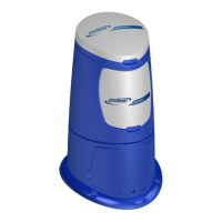
4.2.1 Pulsar®PrecisionComponents
See the Components List on page 8.