Pulsar® Precision Operaon and Installaon Manual (Model PS-1HCE) Rev 2.0 04/2022
12
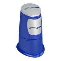
5.2 Install the Flow Switch
Install the ow switch upstream of the booster pump sucon in horizontal or vercal pipe
with upward ow direcon:
1. Drill and tap a 1/2" NPT hole just upstream of the booster pump sucon.
2. In horizontal pipe, the tapped hole should be on the side parallel to the ground or a
lile lower to ensure the posive presence of ow. See Figure 5.
3. In the vercal pipe, the tapped hole should be in the upward direcon of the ow.
See Figure 6.
Cauon: Do not install the ow switch on top of the pipe or in vercal piping with ow
going down. This may cause false “no ow” readings in pipes that don’t always
run full.
4. Use sucient plumber's tape on the ow switch threads to ensure a good seal.
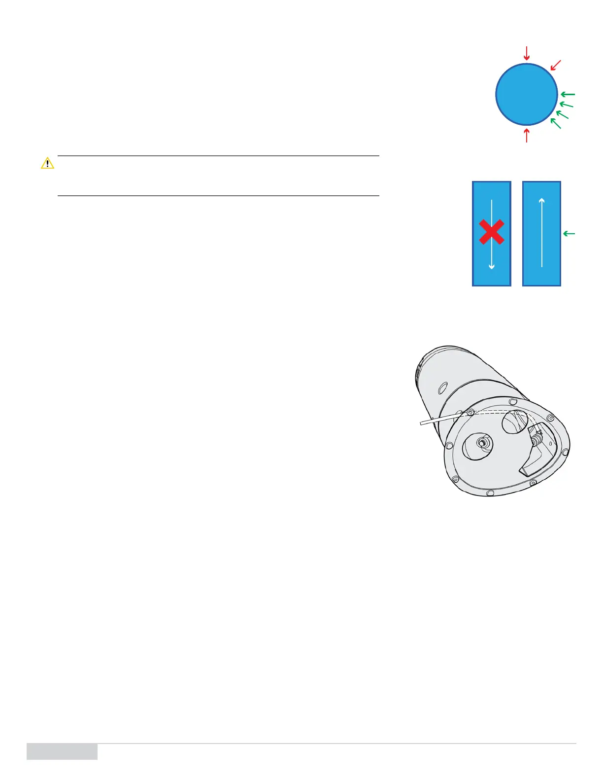
5.3 Feeder Setup - Connect the Discharge Tubing Line
To connect the discharge tubing line of the feeder to the venturi sucon:
1. Remove the hopper (top half) of the feeder and place it on the oor.
2. Remove the le and right base covers to expose the discharge piping check valve
and tubing connector.
3. Esmate how much tubing needed to make the connecon between the feeder and
venturi and cut the appropriate tubing length using tubing cuers.
4. Manipulang the feeder base for easier access, connect the ½" OD polyethylene
tubing to the tubing connector.
5. Wind the other end of the tubing through the hole in the base so that it comes out of
the back of the base. See Figure 7.
6. Connect the tubing to the tubing connector on the venturi sucon.
7. Use a wrench, if necessary, to secure the tubing onto the tubing connectors.
5.4 Feeder Setup - Connect the Inlet Tubing Line
To connect the inlet tubing line of the feeder to the inlet manifold:
1. Replace the hopper back onto the feeder base.
2. Install the 1/2" ball valve, strainer, ow meter and male threaded tubing connector
at the booster pump discharge prior to the venturi. (Install ball valve prior to strainer
and ow meter).
3. Install the ½” female threaded tubing connector on the ½” male threads at the back of the feeder hopper
4. Esmate how much tubing is needed to make the connecon between the feeder and venturi and cut the appropriate tubing length using
tubing cuers.
5. Using the appropriate tubing connectors, connect the feeder inlet to the booster pump discharge.
5.5 Mount the Control Box
Open the control box cover to access the mounng holes of the control box.
1. The control box mounng holes are located on the outside of the waterght gasket.
2. Select the proper bolt size and material for compability to box and wall construcon.
Figure5. Flow switch install in horizontal pipe
Figure6. Flow switch install in vercal pipe
Figure7. Discharge Tubing Connecon