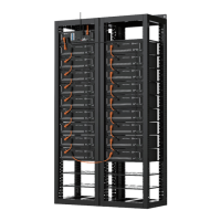
The Pylontech PowerCube-H1/H2-V2 is a high-voltage Lithium-Ion Phosphate Battery Energy Storage System (BESS) designed to provide reliable power for various equipment and systems. It is particularly suited for applications requiring high power output, limited installation space, restricted load-bearing capacity, and a long cycle life.
Function Description:
The PowerCube-H1/H2-V2 system operates as a high-voltage DC system. It consists of multiple battery modules (H48050 or H48074) and a control module (SC1000-100S-V2). The system can be configured with multiple battery strings connected in parallel via CAN communication, with one battery controller acting as the master and the others as slaves. The control module manages the battery system, including charging, discharging, and communication with external devices like Power Conversion Systems (PCS) or inverters. It features a power switch for turning the system ON/OFF, a start button for initiating operation, and various communication ports (RS232, CAN, LAN, RS485, USB) for debugging, external communication, and data transfer. The system also includes dry contact terminals for input/output signals such as wake-up, emergency stop, stop charge, stop discharge, error indication, and current limit.
Important Technical Specifications:
- Product Name: LFP Lithium Ion Energy Storage System
- Cell Technology: LiFePO4
- System Voltage: <1000V
- Battery System Capacity (kWh):
- PowerCube-H1-V2: 2.4 × n (where n = 5~18 modules)
- PowerCube-H2-V2: 3.552 × n (where n = 5~18 modules)
- Battery System Voltage (Vdc): 48 × n (where n = 5~18 modules)
- Battery Module Types: H48050 (50Ah) and H48074 (74Ah)
- Battery Module Capacity (kWh): H48050 (2.4 kWh), H48074 (3.552 kWh)
- Battery Charge Upper-Voltage (Vdc): 54 × n (where n = 5~18)
- Battery Module Discharge Lower-Voltage (Vdc): 43.5 × n (where n = 5~18)
- Control Module Type: SC1000-100S-V2
- Battery System Charge Current (Nominal/Max): 25A/50A (H1), 37A/74A (H2)
- Battery System Discharge Current (Nominal/Max): 25A/50A (H1), 37A/74A (H2)
- Efficiency (@0.5C-rate): 96%
- Depth of Discharge: 95%
- Communication: Modbus RTU/CAN/LAN
- Short circuit rating/Duration: <3000A for 2ms
- Protection Class: IP20
- Cooling Type: Natural convection
- Operation Temperature: 0~50°C (Optimum: 18~28°C)
- Storage Temperature: -20~60°C
- Humidity: 5~95%
- Operation Cycle Life: 5,000 cycles
- Operation Life (Years): 15+
- Product Certificates: IEC62619, IEC63056, RED, CE LVD, VDE2510-50, IEC62040-1, UN38.3
- Dimensions (WDH mm):
- Battery Module: 442×390×100 (H48050), 442×390×132 (H48074)
- Control Module: 442×390×132
- Weight (kg):
- Battery Module: 24 (H48050), 32 (H48074)
- Control Module: 9
Usage Features:
- Installation: Requires qualified personnel due to high voltage. The battery rack is IP00 and must be installed in a restricted access area. Mechanical installation involves fixing the rack to the basement and wall, then installing battery and control modules using screws. Proper grounding is essential, with a grounding resistance of ≤100 mΩ.
- Cable Connection: Power cables use water-proofed AMPHENOL connectors and must be connected correctly (orange to orange, black to black) to avoid personal injury. Communication cables connect battery modules in series and the master control module to external devices.
- System Turn On/Off:
- Turn On: Involves switching on external power/PCS, then turning on slave control modules one by one, followed by the master control module. The "POWER SWITCH" and "Start Button" on each control module are used. A 3-minute interval is recommended between power switch operations.
- Black Start: Long press the start button for 30 seconds after power on to activate.
- Pre-charge Function (Soft Start): Automatically works during parallel operation to prevent short circuits.
- Turn Off: Soft-off the PCS, turn off the switch between PCS and battery strings, turn off "Power Switch" of all BMS, and then turn off the UPS if configured.
- Communication Address (ADD Switch): A 6-bit dial switch on the control module is used to manually assign communication addresses. The 6th bit activates a 120Ω terminal resistance, which should be ON for the first and last nodes in a multi-string setup. For single-group setups, the master control module's address is set to 1. For multi-group setups, each control module must have a different address (1-7), and the V2 version control module must be the master if both V1 and V2 versions are present.
- Status Indicators: LEDs on the battery modules and control module indicate status (RUN, Alarm, Protection) and State of Charge (SOC). Four green lamps represent 25% capacity each.
- WIFI: Supports cloud platform functions.
- USB: Used for product updates and data downloading.
Maintenance Features:
- Troubleshooting: The manual provides a detailed table of failure modes, possible reasons, and solutions, covering issues like power cable problems, internal communication errors, voltage sensor errors, temperature sensor errors, relay errors, battery cell damage, shutdown circuit errors, BMIC errors, BMS internal bus errors, self-test errors, and communication errors between master and slave BMS.
- Component Replacement: Instructions are provided for replacing battery modules and control modules, emphasizing the need to turn off the entire battery string's power and ensure D+/D- terminals are without power before handling. New battery modules should be charged to 100% SOC before installation.
- Periodical Maintenance:
- Voltage Inspection: Check system and single cell voltages for abnormalities via the monitor system.
- SOC Inspection: Check battery string SOC for abnormalities via the monitor system.
- Cables Inspection: Visually inspect all cables for breakage, aging, or looseness.
- Balancing: Perform balancing maintenance (charge to full) every 3 months, or allow automatic balancing via communication with external devices.
- Output Relay Inspection: Under low load, control the output relay OFF and ON to check for click sounds, indicating normal operation.
- History Inspection: Analyze history records for alarms and protections, and their reasons.
- Shutdown and Maintenance: System maintenance is recommended every 6 months, often during EMS restart.
- Storage: For long-term storage (>3 months), battery cells should be stored at 5~45°C, <65% relative humidity, and in a non-corrosive gas environment. Battery modules should be charged to 50~55% SoC. Chemical activation (discharge and charge) is recommended every 3 months, with a maximum interval of 6 months. Failure to follow these instructions can significantly reduce cycle life.
- Capacity Expansion: New battery modules can be added to an existing system at any time, provided the existing system is fully charged. In serial connection systems, the new module will follow the worst SOH condition of the existing modules.
- Recycling: Damaged batteries must be recycled according to local regulations (e.g., Regulation (EC) N° 1013/2006 in the European Union) using best available techniques for relevant recycling efficiency.