2.5. Control Module Specification
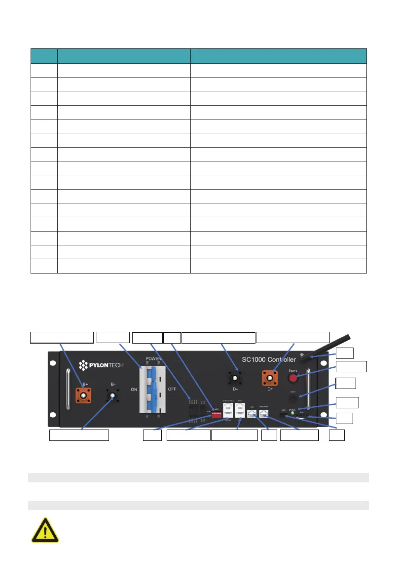
2.5.1. Control Module Front Interface
No. Product Type SC1000-100S-V2
Related Product
Controller Working Voltage
System Operation Voltage(Vdc)
Charge Current(Max.)(A)
Discharge Voltage(Vdc)
Discharge Current(Max.)(A)
Self-consumption Power(W)
Dimension(W*D*H,mm)
Communication
Protection Class
Weight(kg)
Operation Life(Years)
Operation Temperature(
℃
)
Storage Temperature(
℃
)
Product Certificate
H48050/H48074
200~1000Vdc
200~1000
80
200~1000
80
8
442*390*132
Modbus RTU\CAN\LAN
IP20
9
15+
-20~65
-40~80
TUV, CE
1
2
3
4
5
6
7
8
9
10
11
12
13
14
15
* Maximum current is the values only for controller, the current value of the system is based on
the battery module
Power Terminal+ To battery
Power Switch
Internal CAN A&B
Power Terminal- To battery
External Power Terminal - To PCS
WIFI
Reset RS232/External CAN LAN
SOC
USB
Linkport to BAT
External Power Terminal + To PCS
SC1000-100S-V2
Power Switch
Power Terminal B+/B-
To connect battery module power cables in series.
Switch the battery system’s (control module and high voltage DC power) ON/OFF.
Caution: When the breaker is tripped off because of over current or short circuit, must wait after
30 minutes to turn on it again, otherwise may cause the breaker damage.
10
/
42