.
Start Button
Start function: press more than 5 sec until the buzzer rings, to turn on controller.
Black start function: when system turned on and during self-check process , press and hold
the start button again for more than 10sec, and relay will close for 10 mins.
LAN
Console Communication Terminal: (RJ45 port) follow Modbus TCP protocol, only used for communication
between the master control module and upper controller.
RS485(Link Port A and B)
RS485 Communication Terminal: (RJ45 RS485 Link port A) follow Modbus RTU protocol, for external
communication between battery system and Power Conversion System.
In a multi-strings structure, these two ports (RJ45 RS485 Link port A & B) are used to connect the two
control modules of the front and rear nodes.
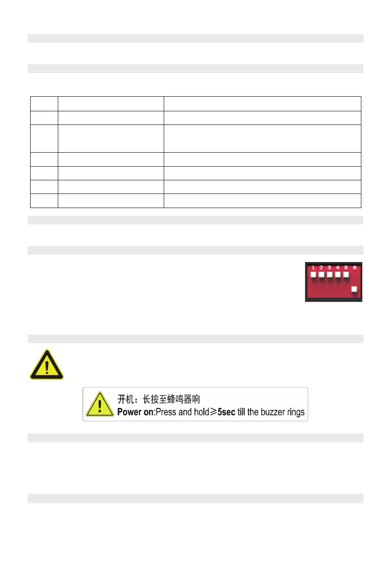
ADD
ADD Switch is a 6 bit dial switches to manually distribute the communication address of
the battery system. Downward position is OFF, means “0”. Upward position is ON,
means “1”. For battery controller, 1st bit to 5th bit is for address allocation, and the 6th
bit dial switch support a 120Ω resistance (Terminal Resistance), the upward
position(ON) of the 6th bit means access the resistance, and the downward
position(OFF) means no access resistance. The terminal resistance needs to be activat-
ed ON at the first and last node.
Reset
Reset Button: Long press this button to restart the battery system.
Dry Contact Terminal
Dry Contact Terminal: provided 2 input and 4 output dry contact signal.
External Power Terminal D+/D-
Connect battery system with Power Conversion System.
Function
Internal Using ONLY
Stop Charge
Stop Discharge
Error
Current Limit
Open and close state
For wake up signal serial connection using ONLY.
Always close, when open shall stop charge.
Always close, when open shall stop discharge.
Always close, when open shall stop operation
Always close, when open shall limit current to ≤0.2C-rate
In/out
In1
Out1
Out2
Out3
Out4
For wake up or
For Emergency Stop signal**
Always close, when open will switch off the system.In2
11
/
42