With SC1000-100S-V2, there DONOT need a MBMS for multi-groups operation.
For the existing installation (with old SC1000-100S) capacity expansion or BMS replacement activity,
please REMOVE the MBMS and add on the SC1000-100S-V2 at the master position for further communi-
cation with existing inverter directly.
The communication cable shall connect follow below diagram, from the first BMS ‘Link Port B’ to the
second BMS ‘RS485 / Link Port A’, from the second BMS ‘Link Port B’ to the third BMS ‘RS485 / Link Port
A’, all the way to the last BMS’ ‘RS485 / Link Port A’. The BMS with ‘RS485 / Link Port A’ EMPTY is defined
as the master BMS, and further communication with the inverter.
3.6.4.2. For Multi-groups communication wiring connection
The communication cable shall connect follow below diagram.
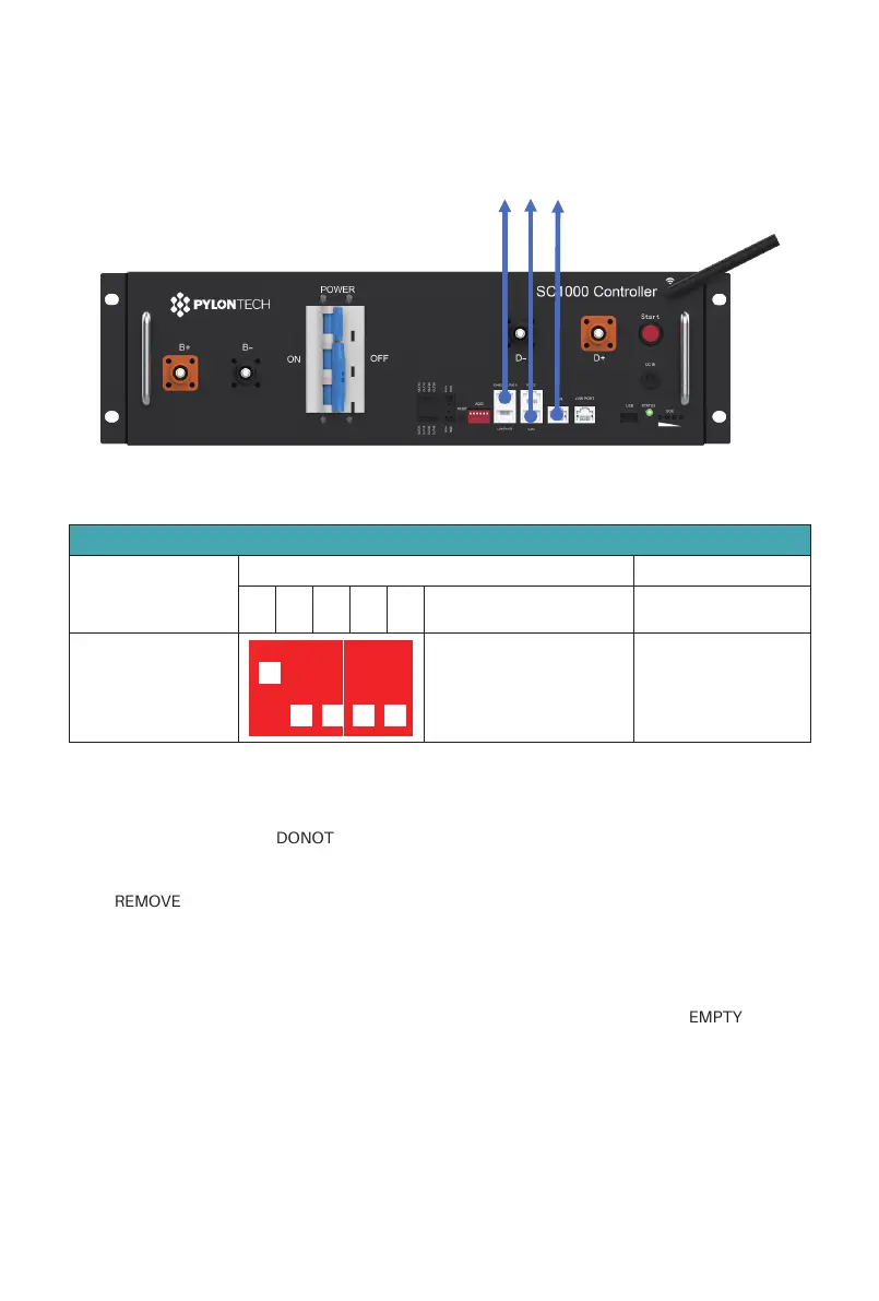
3.6.4.1. For single group communication wiring connection to inverter/upper controller
3.6.4. Communication wiring connection of the master and slave control modules
To inverter/upper controller
The ADD address shall set follow table,
Table of the control module ADD address setting for Single-group
CAN Address
Master
Address dial bit
6(Terminal Resistance)
1
Master or slave
relationship
No requirement.
1 2 3 4 5
54321
26
/
42