25
TD-001517-01
K.2 Series Service Manual
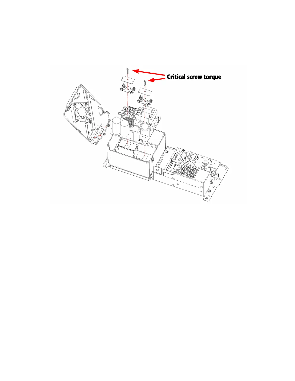
11. Remove the 2 long machine screws, 2 metal springs, and 2 plastic clamps. See Figure 6.2.7.
12. Lift the AMP/PSU board straight out of the chassis.
Important note: Carefully lift the AMP/PSU board out of the chassis in a straight upward direction to reduce the risk of
misaligning the insulation pads on the heatsink. If the insulation pads are moved in this step, they must be realigned
when installing a new AMP/PSU board.
Installation
Before reinstalling an AMP/PSU board, it’s very important to the take extra time to inspect the power MOSFETs on the bot-
tom of the PCB, reapply thermal grease to the insulation pads, and align them.
1. Prepare the AMP/PSU board for installation. Reapply a thin but uniform layer of thermal grease to the 4 insulation pads
on the heatsink.
2. Carefully align and place the AMP/PSU board into the heatsink cavity, verifying that the body of the power components
(MOSFETs and diodes) on the bottom of the PCB is not making contact with the metal heatsink.
Important note: If the power components are touching the metal heatsink, a catastrophic failure could occur when
powering up for the first time after installation.
3. Fasten the 7 short machine screws to secure the AMP/PSU board to the heatsink chassis.
4. Install the 2 plastic clamps, 2 metal springs, and 2 long machine screws, specifically in that order.
5. Fasten the 2 long machine screws at a torque of 28.8 kgf-cm (25 in-lbs).
Important note: The torque specification on these 2 screws is very critical to ensure good heat transfer between the
electrical component and heatsink. Sufficient clamp force is required to achieve the best result.
Figure 6.2.7 - AMP/PSU removal and installation, including output board attached to metal cover.
 Loading...


