Technical Service Manual 9
PowerLight 6.0 II, PowerLight 6.0
PFC
, and PowerLight 9.0
PFC
Fan (4-pin header;
2 pins per fan)
Power supply
(wires 0 through 4)
Housekeeping
supply
Display
board
(via multi-
conductor
ribbon cable)
From input
board
(detachable
latching header)
(2 bundles)
Preparing the audio modules for removal
4. There are two fishpaper insulators on each audio module.
Remove them by lifting them straight up off the heat sinks. Do
not slide them forward or backward.
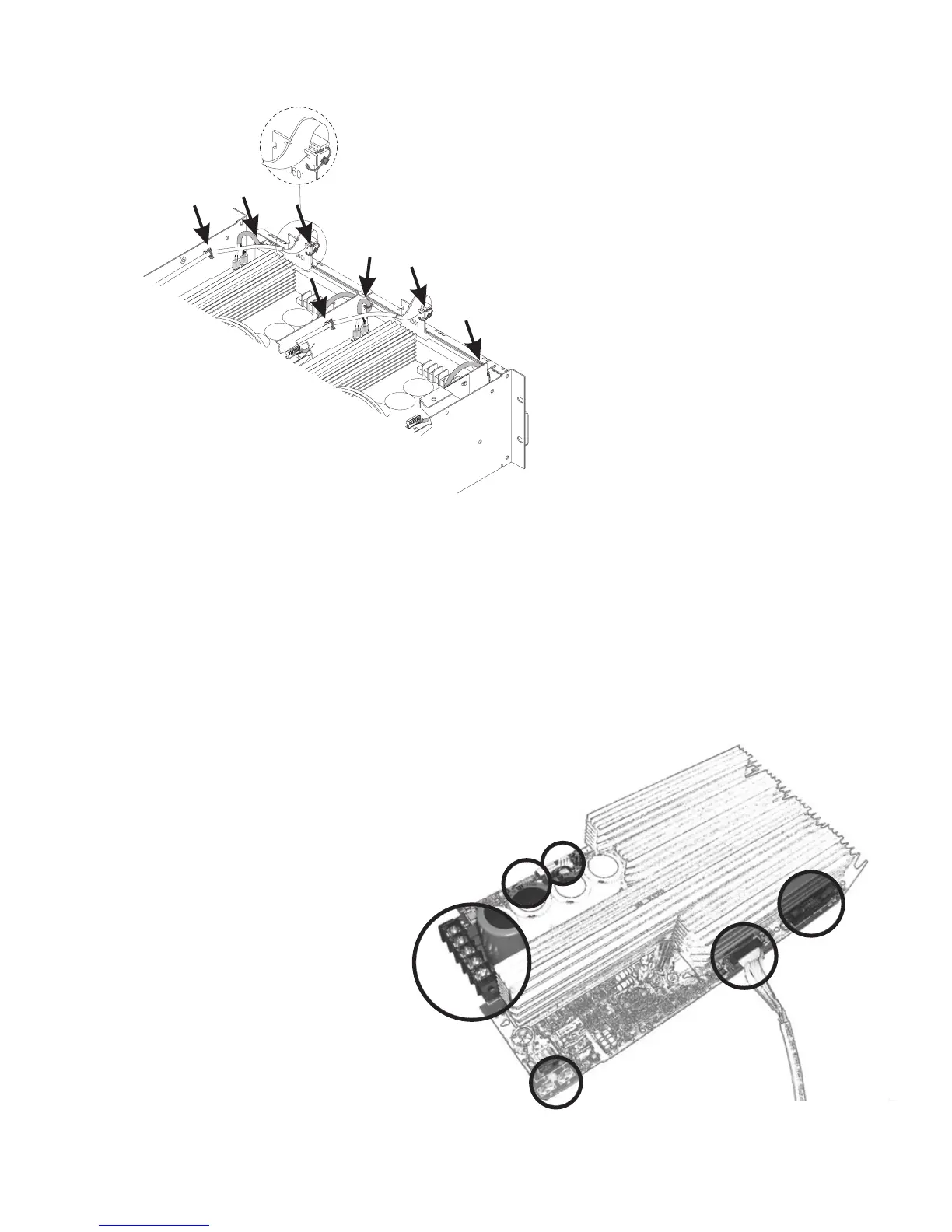
5. Cut the tie wraps in the seven locations shown in Figure 2.2.
6. Disconnect the display board header in front of each module.
7. Using needle-nose pliers, grasp one of the housekeeping
supply connectors and disconnect it from the modules (see
Figure X.X). Repeat for the other(s).
8. Disconnect the fan connections (two on each module).
9. Spread open the latches on the power
supply control interface connections and
disconnect the headers from the
modules.
10. Remove the two screws that secure the
audio module to the chassis partition.
One screw is at the corner near the
power supply connections, and the other
is about 6 cm (2.5 inches) behind the
housekeeping supply connections.
11. Locate the power supply connections, the
five screw terminals at the front of each
module. Loosen them and remove the
wires.
12. There may be an adhesive rubber foot
wedged in front of each module circuit board.
Grasp it with the needle-nose pliers and pull
it out.
Removing the chassis rear panel
13. Remove the four screws on the rear panel
(see Figure 2.4).
14. Tip the amplifier up on its right side (the side
opposite the power cord). There are three flat
head screws in a line along the center of the
side panel. Remove them.
15. Remove the two pan head screws on the rear
rack tab.
16. Set the amp back down and remove the two
pan head screws from the other rear rack tab.
17. Remove the two screws under the power
cord.
18. Tip the chassis rear panel back and discon-
nect the header from the input board.
19. Lift the fan wires clear of the heat sinks on
the audio modules.
Power supply
control (8-pin
header)
Figure 2.2. Seven tie wraps.
Figure 2.3. The connections to
the audio module.

 Loading...


