Technical Service Manual 13
PowerLight 6.0 II, PowerLight 6.0
PFC
, and PowerLight 9.0
PFC
Key QSC Part Description Qty.
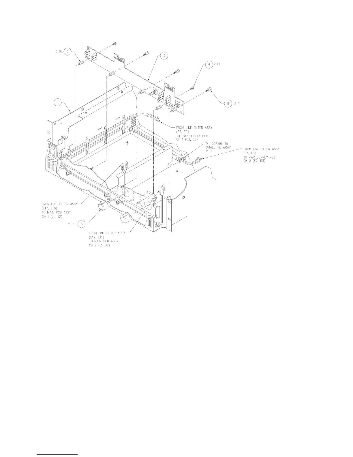
1
2
3
4
5
6
CH-000078-00 Chassis, PL 9.0 1
HW-000079-00 Hex standoff #6-32 x 9/16” 5
WP-000176-00 Display PCB assy. 1
SC-060042-PP Screw, #6-32 × 1/4”, SEMS 2
HW-060080-HW Hex standoff #6-32 x 1/2” 3
PL-000054-00 Knob fab. 2
2.2 The display board
The display board contains the signal metering, clip, power, and
status LEDs. It also holds the two gain potentiometers. LED failures
are very rare, but you will need to remove the board if the gain
pots become damaged or badly contaminated. See Figure 2.7.
2.3 AC line filter
The AC line filter is an important part of the amplifier because it
reduces noise and interference from the internal switching
circuitry to prevent its radiation into the AC wiring. It also contains
part of the housekeeping supplies for the two audio modules;
without the housekeeping supplies, the amplifier’s power supply
modules will not start up even if they are in working order.
The line filters are the same among the three amplifier models,
but the 120-volt and 230-volt versions are not interchangeable.
See Figure 2.8.
Figure 5.7. Removing or installing the display board.

 Loading...


