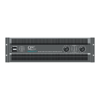
Technical Service Manual 3
PowerLight 6.0 II, PowerLight 6.0
PFC
, and PowerLight 9.0
PFC
Table of Contents
Performance Specifications ............................................................................................................................................................................................... 4
1. Introduction ..................................................................................................................................................................................................... 5
1.1 Service bulletins.............................................................................................................................................................................................................. 5
1.2 The well-equipped service bench ............................................................................................................................................................................... 5
1.3 Working with surface-mount components................................................................................................................................................................. 5
Two-terminal components (resistors, capacitors, diodes, etc.)............................................................................................................................................................. 5
Multi-pin components (ICs, etc.) ........................................................................................................................................................................................................ 6
Three-terminal components (transistors, etc.) .................................................................................................................................................................................... 6
1.4 Series description ........................................................................................................................................................................................................... 6
1.5 Technical descriptions and theory of operation ........................................................................................................................................................ 7
Power supplies ................................................................................................................................................................................................................................. 7
Audio circuitry ................................................................................................................................................................................................................................... 7
2. Servicing the amplifier.................................................................................................................................................................................. 8
2.1 Mechanical disassembly and reassembly ................................................................................................................................................................. 8
Introduction ...................................................................................................................................................................................................................................... 8
Tools and materials needed .............................................................................................................................................................................................................. 8
Disassembly ..................................................................................................................................................................................................................................... 8
Reassembly .................................................................................................................................................................................................................................... 11
2.2 The display board.......................................................................................................................................................................................................... 13
2.3 AC line filter ................................................................................................................................................................................................................... 13
2.4 Power supply servicing................................................................................................................................................................................................ 15
Bench testing power supply modules .............................................................................................................................................................................................. 15
Replacing switching MOSFETs in PFC models .................................................................................................................................................................................. 15
Suggestions for troubleshooting ..................................................................................................................................................................................................... 17
Adjusting and calibrating the power supply module ......................................................................................................................................................................... 18
2.5 AC voltage conversions................................................................................................................................................................................................ 22
2.6 Bias adjustments ........................................................................................................................................................................................................... 22
3. Troubleshooting............................................................................................................................................................................................ 23
3.1 Initial check ................................................................................................................................................................................................................... 23
3.2 Preliminary troubleshooting ........................................................................................................................................................................................ 23
3.3 Further troubleshooting ................................................................................................................................................................................................ 24
4. Parts ................................................................................................................................................................................................................. 25
4.1 Semiconductor package descriptions and pinouts ................................................................................................................................................ 25
4.2 Parts lists ........................................................................................................................................................................................................................ 33
Chassis Assembly (QSC part #WP-000268-00) ................................................................................................................................................................................ 33
Chassis Assembly (QSC part # WP-000268-02) ............................................................................................................................................................................... 34
Chassis Assembly (QSC part # WP-000260-00) ............................................................................................................................................................................... 35
Chassis Assembly (QSC part # WP-000260-02) ............................................................................................................................................................................... 36
Chassis Assembly (QSC part # WP-000170-00) ............................................................................................................................................................................... 37
Chassis Assembly (QSC part # WP-000170-02) ............................................................................................................................................................................... 38
Chassis Assembly, Rear (QSC part # WP-000271-00) ....................................................................................................................................................................... 39
Chassis Assembly, Rear (QSC part # WP-000264-00) ....................................................................................................................................................................... 39
Chassis Assembly, Rear (QSC Part # WP-000172-00) ....................................................................................................................................................................... 40
Output PCB Assembly (QSC part # WP-000179-00) ......................................................................................................................................................................... 40
Input PCB Assembly (QSC part # WP-000272-00) ............................................................................................................................................................................ 40
Input PCB Assembly (QSC part # WP-000265-00) ............................................................................................................................................................................ 41
Input PCB Assembly (QSC part # WP-000175-00) ............................................................................................................................................................................ 41
Input Daughterboard Assembly (QSC part # WP-000178-00)........................................................................................................................................................... 42
Audio Channel Module Assembly (QSC part number WP-000276-00) ............................................................................................................................................. 42
Audio Channel Module Assembly (QSC part # WP-000182-00) ....................................................................................................................................................... 46
Power Supply Assembly (QSC part # WP-000266-00)...................................................................................................................................................................... 50
Power Supply Assembly (QSC part # WP-000266-02)...................................................................................................................................................................... 52
Power Supply Assembly (QSC part # WP-000262-00)...................................................................................................................................................................... 55
Power Supply Assembly (QSC part # WP-000262-02)...................................................................................................................................................................... 56
Power Supply Controller Assembly (QSC part # WP-000263-00) ...................................................................................................................................................... 58
Power Supply Assembly (QSC part # WP-000173-00)...................................................................................................................................................................... 60
Power Supply Assembly (QSC part # WP-000180-00)...................................................................................................................................................................... 61
Power Supply Controller Assembly (QSC part # WP-000174-00) ...................................................................................................................................................... 63
Display PCB Assembly (QSC part number WP-000176-00) ............................................................................................................................................................... 64
Line Filter Assembly (QSC part number WP-000177-00) ................................................................................................................................................................... 66
Line Filter Assembly (QSC part number WP-000181-00) ................................................................................................................................................................... 66
Matched FETs ................................................................................................................................................................................................................................. 67
5. Schematic diagrams .................................................................................................................................................................................... 68

 Loading...