8 QSC Audio Products, Inc.
TD-000083-00
2. Servicing the amplifier
2.1 Mechanical disassembly and reassembly
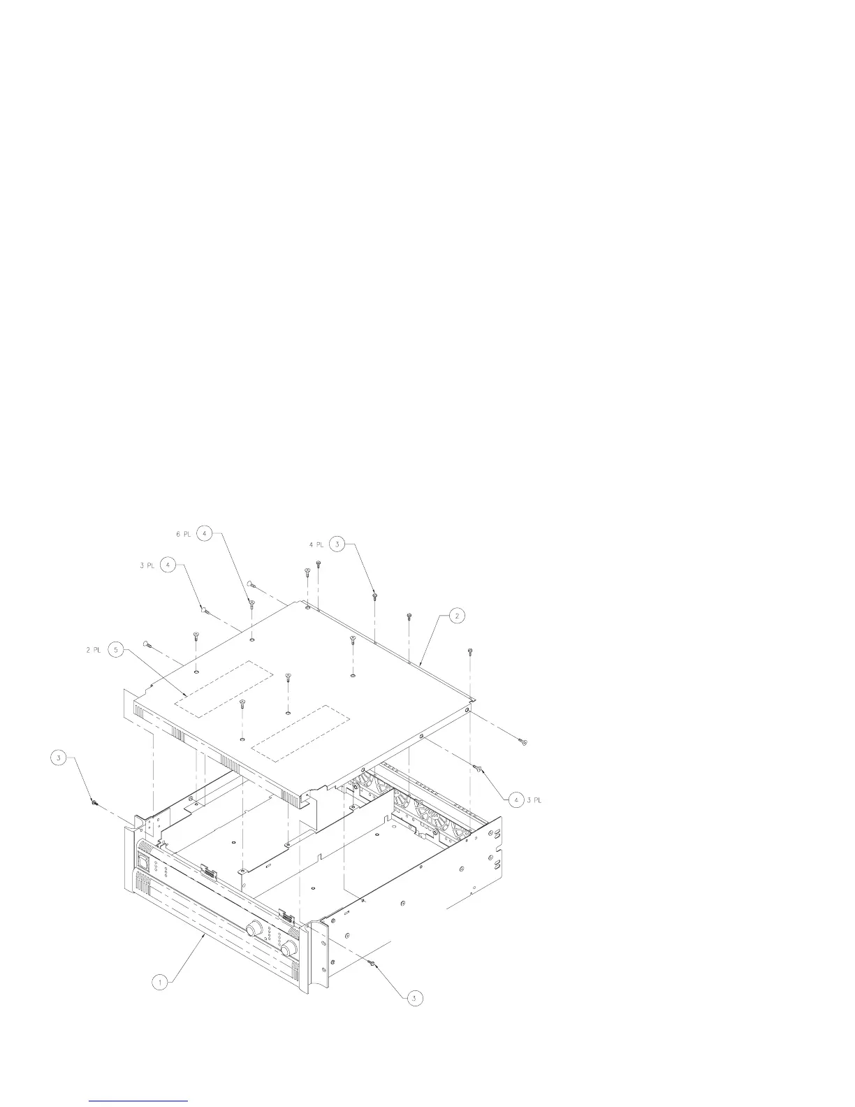
Key QSC Part Description Qty.
1
2
3
4
5
WP-000170-XX Chassis assy., PL 9.0 1
CH-000079-00 Top cover 1
SC-082051-PL Screw, #8-32 × 5/16”, pan head 6
SC-080051-PU Screw, #8-32 × 5/16”, flat head 12
PL-000104-00 Insulator, high volt. 2
Introduction
Replacing components will usually require removing the affected
modules from the amplifier chassis. The two channels each have
their own power supply module and audio module, and they share
the line filter assembly and the input, output, and display board
assemblies.
Within the chassis, the power supply modules are on the bottom,
and the audio modules are on top. Getting at a power supply
module requires removal of its audio module first.
The following instructions describe the procedure for removing
both audio and both power supply modules. However, if you only
need to work on one channel, you do not need to remove the
modules from the other.
Tools and materials needed
• Philips screwdriver
• Diagonal cutters
• Tie wraps
• Needle-nose pliers
• Adhesive rubber foot (one per channel), QSC part # QQ-
QQQQQQ-QQ or equivalent
• 5/64” hex (Allen) key
• 11/32” nutdriver or socket wrench
• Isopropyl alcohol and a small brush
Disassembly
Removing the top cover
1. Disconnect the amplifier from AC power and allow at least 10
minutes for internal voltages to bleed down.
2. A total of 18 screws—six with pan heads and twelve with flat
heads—hold the top cover to the chassis. Using a Philips
screwdriver, remove them and set them aside. See Figure 2.1.
3. Lift the top cover up at the front until it clears the side rack ear
pieces, then lift it off the chassis. If the front of the cover is
bent or dented, make sure the front edge clears the two
display board headers.
Figure 2.1. Removing or installing
the top cover.

 Loading...


