Technical Service Manual 15
PowerLight 6.0 II, PowerLight 6.0
PFC
, and PowerLight 9.0
PFC
2.4 Power supply servicing
Bench testing power supply modules
The housekeeping supplies provide electrical power to certain
control circuitry in their respective audio channel modules. The
control circuitry in turn enables the power supply module to
operate. Thus, a power supply module normally will not operate
when it is not connected to an audio channel.
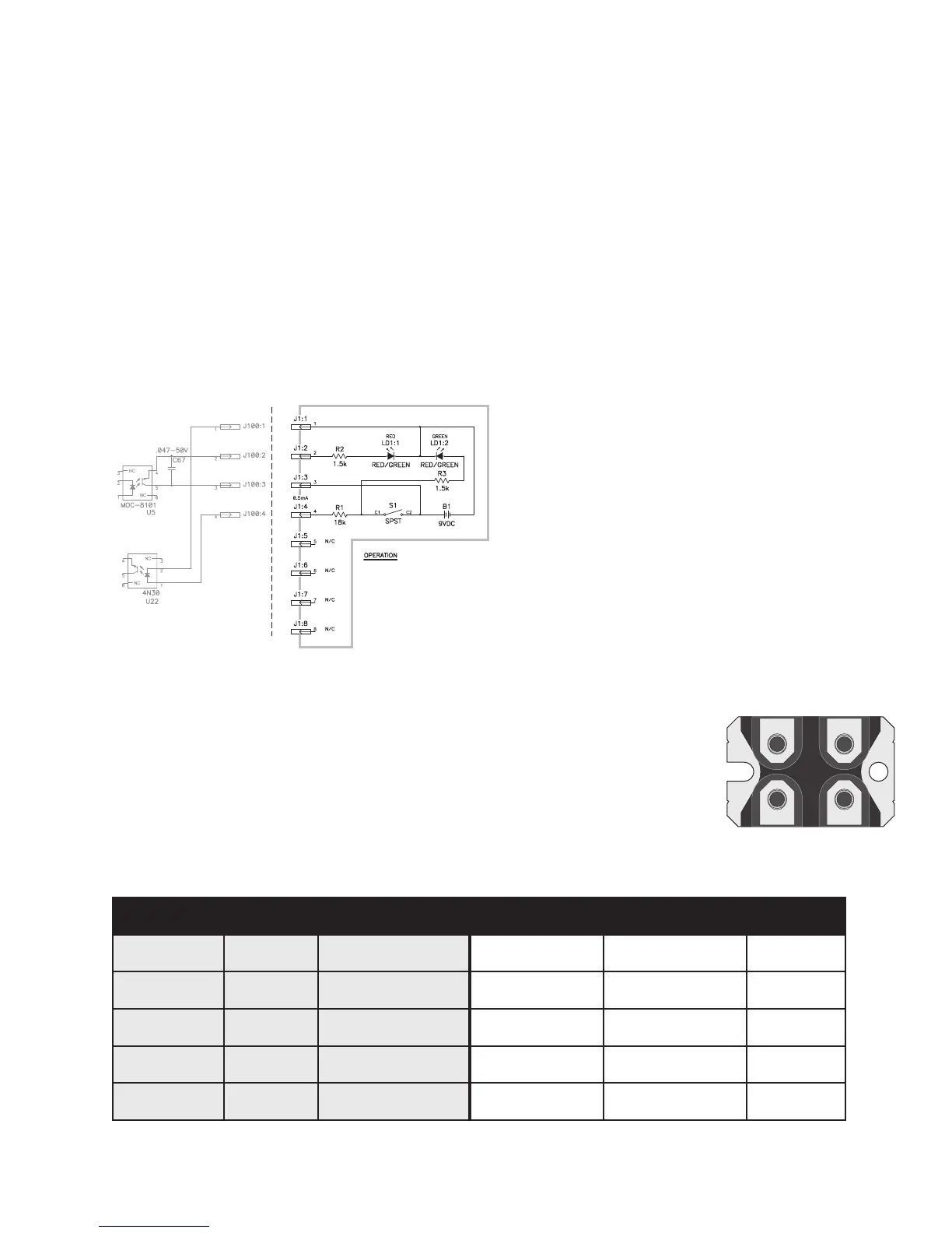
The remote control circuit shown in Figure 2.9 allows the power
supply module to operate without an audio channel module
connected. This is useful for verifying the power supply’s operation
independently of other amplifier circuitry.
Parts list
• 8-pin header (J1)
• 9-volt battery (B1)
• SPST switch (S1)
• Three-lead tri-color LED (LD1)
• 18 kΩ resistor (R1)
• Two 1.5 kΩ resistors (R2 and R3)
ecnerefertraP #trapweN noitpircseD #trapdlosecalper… noitpircseD ?sledomhcihW
4Q&,3Q,2Q,1Q
00-881000-DQ TEFSOMA5505N55FXI
00-911000-DQTEFSOMA8405N84FXI
sledomllA
8R&,7R,6R,5R
01-10574.-ER 57.4 ΩΩ
Ω
ΩΩ rotsiserttaw-¼
01-20001.-ER1Ω rotsiserttaw-¼
sledomllA
8D&,7D,2D,1D
00-381000-DQ edoid80SPE06
00-621000-DQedoidA60-06IESD
ylnosledomV021
8D&,7D,2D,1D
00-281000-DQ edoid21SPE06
00-761000-DQedoid21-06IESD
ylnosledomV032
02C
00-900014-AC roticapacV052Fµ1.0
00-004743-ACroticapacV004Fµ740.0
sledomllA
Replacement parts
Replacing switching MOSFETs in PFC models
Replacing the power MOSFETs and their associated components
requires that the power supply modules be removed from the
amplifier.
Tools and materials required:
• Soldering iron
• Rosin-core solder (60/40 or 63/37 eutectic type)
• Long-nose pliers
• #1 and #2 Philips screwdrivers
• Thermal grease (heat sink compound)
• Small diagonal cutters
• Desoldering equipment or solder braid
• Micro-torque wrench with 9/64” Allen (hex) and #1 Philips bits
If fuse F1 on the power supply module’s printed circuit board (PCB)
is blown, you will also need a 1A 250V 5×20 mm slow-blow fuse
(QSC part # MS-000113-00) to replace it with. Also, the alumina
insulator between the diodes and the heat sink is very fragile and
often breaks when the diodes are removed; replace it with QSC
part # PL-000085-00.
To ensure that the devices will share power equally, the four
MOSFETs must have similar V
DSS
. For a set of four matched
MOSFETs, as pre-sorted by QSC production, order QSC part #
WP-000056-00.
Procedure: replacing Q1, Q2, Q3, and Q4
1. Remove the heat sink assembly to which the MOSFETs are
attached.
To do this, remove the clamps on the four diodes (D1, D2, D7,
and D8) to free them from the heat sink. Keep the two mica
insulators (from between the
diodes and clamps) and set
them aside for when you
reassemble the heat sink and
diodes later; they are fragile,
so be careful handling them
but replace any that are
damaged. The QSC part
number is PL-000059-00.
Remove the alumina insulator
Figure 2.10. Bottom view of a
MOSFET
THIS REMOTE CONTROL IS USED TO TURN ON THE
PFC POWER SUPPLY VIA J100 ON THE CONTROLLER
BOARD.
CLOSING POWER SWITCH S1 ENABLES THE POWER
SUPPLY, AND LED LD1:2 WILL GLOW GREEN.
LED1:1 WILL ALSO LIGHT, AND THE RESULTING
COLOR WILL BE YELLOW-ORANGE.
WHEN
THE AC INPUT VOLTAGE APPLIED TO THE PS
MODULE REACHES THE TURN-ON THRESHOLD (65
VAC FOR 120V UNIT OR 130 VAC FOR 230V UNIT),
POWER SUPPLY
CONTROLLER BOARD
POWER SUPPLY TEST
REMOTE CONTROLLER
Figure 2.9. Remote controller for power supply testing.

 Loading...


