Technical Service Manual 19
PowerLight 6.0 II, PowerLight 6.0
PFC
, and PowerLight 9.0
PFC
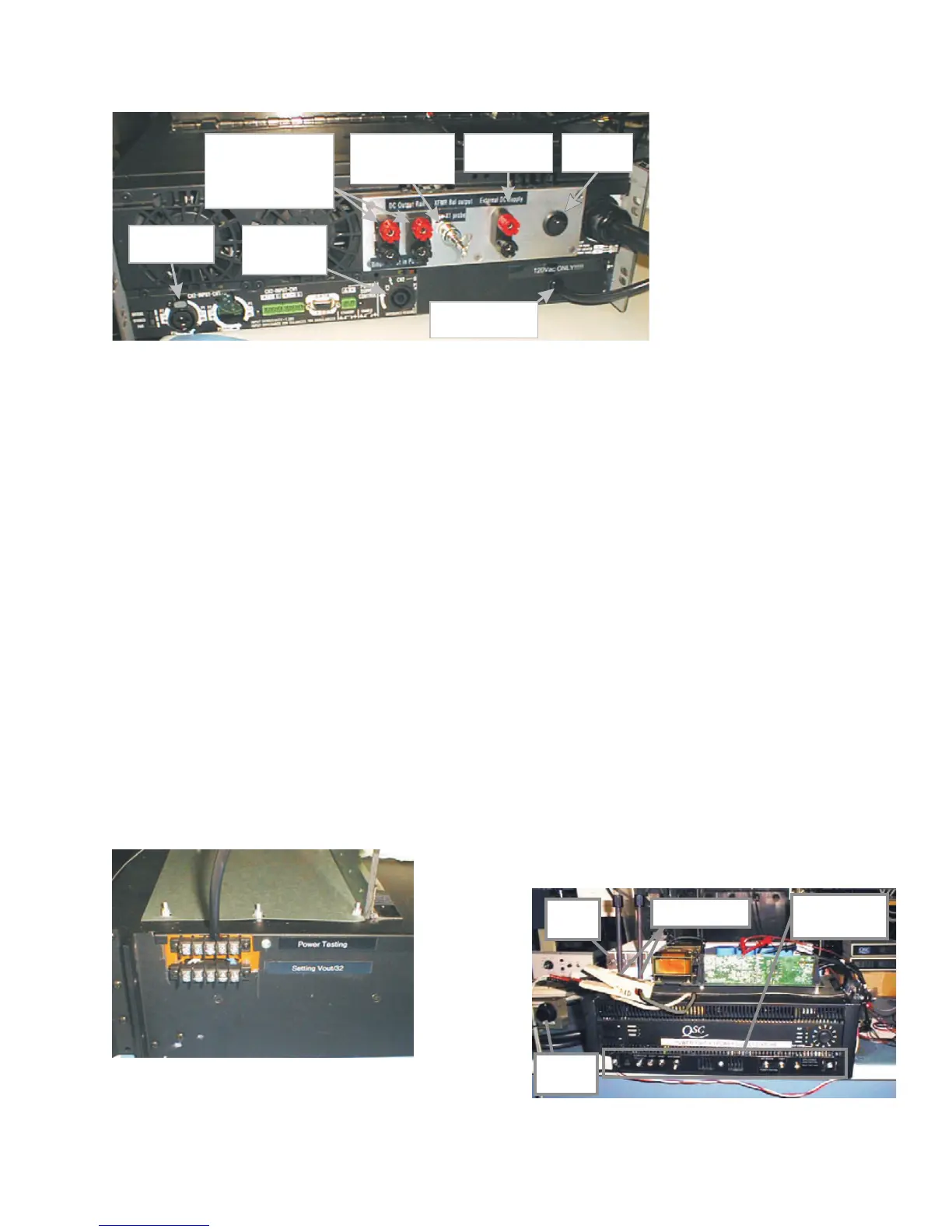
output to the AP workstation and to the load resistors.
• Transformer flux sample. Connect the tip of an oscilloscope’s
×1 probe to the exposed conductor at the tip of this attach-
ment, and connect the probe’s reference clip to the loop. This is
used in the transformer balancing, the third procedure in the
supply module adjustment and calibration.
• DC supply input. This dual binding post set is for connecting
the fixture to the external power supply.
• 120 VAC power cord. This connects to a regular AC outlet and
provides power for the fixture’s “housekeeping” supply, which
powers the various circuits and indicators.
• Housekeeping supply power switch. This small rocker
switch lets you turn off the housekeeping supply when the
fixture is not in use.
• Fixture power cord. This large power cord connects to the
Variac and provides AC power for the power supply module
under test.
Other attachments
See Figure 2.17.
• Lower barrier strip. Connect the supply module’s five black
DC rail wires to the lower barrier strip’s terminals for the first
procedure, setting V
OUT
.
Procedure
1
of
5:
Setting V
OUT
1 Turn off all power to the fixture and turn the Variac all the
way down. Set the power supply module in place atop the
fixture, as shown in Figure 2.18.
2 On the test fixture, set switches V
OUT
/32 and I
SET
in the
up
position. Turn off the fan switch.
3. On the power supply module, disconnect the gate drive cable
(Figure 13).
4. Connect the two AC line wires to the stud terminals on the
PCB: white to E2 on the left, black to E3 on the right. Use the
long insulated threaded posts to secure the wires to the
terminals.
5. Connect the power supply module’s five black DC output
wires, labeled 0 through 4, to the screw terminals on the
lower
barrier strip (Figure 10). Keep them in order; do not
cross any of them.
6. The external power supply has two dual banana sockets—one
is labeled
active
and the other,
dummy
. Connect the fixture’s
dual banana plug to the external power supply’s
active
socket.
7. Plug the AC lines for both the external DC supply and the
fixture into the Variac.
8. Set the CMP boxe’s electronic fuse to a trip threshold of 5
amperes.
Audio signal input
from Audio Precision
workstation
Audio signal output
to Audio Precision
workstation and load
resistors
120 VAC for fixture's
housekeeping supply
(Do not connect to Variac!)
DC high rail outputs: for
PL 9.0 ; for PL 6.0
The two sets of binding posts are
in parallel. Connect DMM #1 to
one set.
191.3 V
166.5 V
PFC PFC
Red = +; Black = -
Transformer flux sample
for balancing procedure.
Connect to oscilloscope
using ×1 probe.
Connect to external DC
supply. Watch polarity:
Red = +; Black = -
Power switch for
housekeeping
supply.
Ext. DC
supply
AC connection
Solid-
state fuse
Switches and
LED indicators
• Upper barrier strip. Connect the
DC rail wires to the upper barrier
strip for the other procedures.
• Control connection. Above the
barrier strips is a multiconductor
cable that connects to the 8-pin
header on the controller card of the
power supply module under test.
• AC wires. Located at the top of the
front panel, these two wires connect
to points E2 and E3 on the supply
module.
Figure 2.17. The fixture’s rear panel.
Figure 2.18. The two barrier strips. Use the lower
one for the first adjustment (setting V
OUT
/32 or V
OUT
/
26.6), and the upper one for the other adjustments. Figure 2.19. The power supply module loaded onto the test fixture.

 Loading...


