ABOUT THE SYSTEM LED STATUS DEFINITIONS
1-10
LAN LED
The system mainboard includes dual GbE network with GbE dedicated management port.
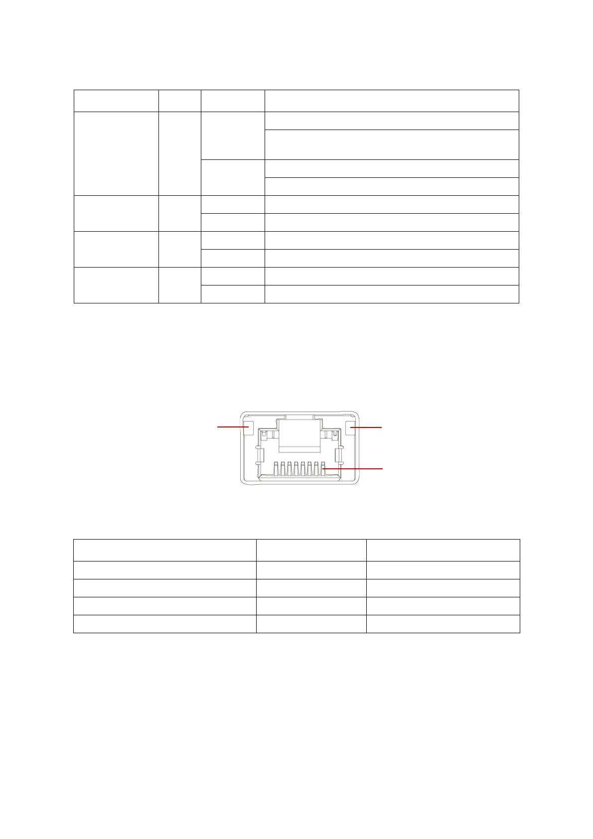
Each RJ45 connector has two built-in LEDs. See the following illustration and table for
details.
Figure 1-10. RJ45 LAN Connector
Fault LED Amber
Blinking
Critical Failure: critical fan, voltage, temperature state.
Non-Critical Failure: non-critical fan, voltage, temperature
state, CPU thermal trip, DC off.
Off
SEL cleared
Last pending warning or error has been de-asserted.
HDD activity Blue
Blinking Hard disk drive access (only on board SATA port)
Off No access (non-SAS)
LAN1 LED Blue
On Link
Blinking LAN access (off when there is traffic)
LAN2 LED Blue
On Link
Blinking LAN access (off when there is traffic)
Table 10: RJ45 LED Description
CONDITION LINK ACTIVITY
Unplugged Off Off
1G active link On amber Blinking green
100M active link On green Blinking green
10M active link Off Blinking green
Table 9: Front Control Panel LED Behavior (Continued)
NAME COLOR CONDITION DESCRIPTION
Link
Activity
PIN 1
Location
 Loading...