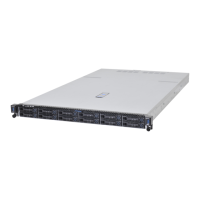
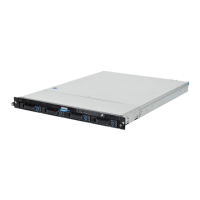
ABOUT THE SYSTEM SYSTEM FRONT VIEW
1-6
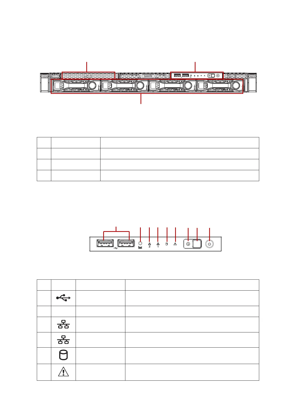
System Front View
Figure 1-3. System Front View
Front Control Panel (FCP)
For purposes of this procedure, the FCP is used for the numbering indicators.
Figure 1-4. Front Control Panel
Table 3: Front Panel View
NO.NAME DESCRIPTION
1 Front control panel See Front Control Panel LED on page 1-9 for further information.
2 HDD bays 4 x 3.5” SAS/SATA HDD
3 SSD tray 2 x SSD
Table 4: Front Control Panel Definition
NO.ICON NAME DESCRIPTION
1 USB ports USB ports 1 & 2
2 Reset button Soft reset system function
3 LAN2 LED LAN access
4 LAN1 LED LAN access
5 HDD activity LED Hard disk drive access
6 Fault LED Provides critical and non-critical failure notification
 Loading...