QUANTECH
36
SECTION 4 - INSTALLATION
FORM QTC4-NM1
ISSUE DATE: 4/2/2018
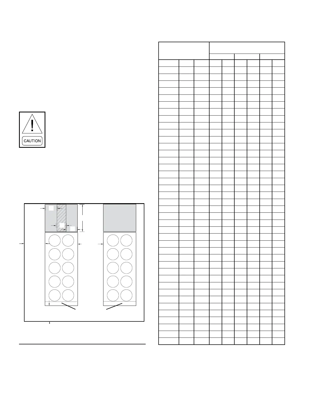
Recommended Minimum Clearances
Recommended clearances for the QTC4 units are:
• Side to wall – 6' (1.8 m)
• Rear to wall – 6' (1.8 m)
• Control panel end to wall – 4' (1.2 m)
• Top – no obstructions whatsoever
• Distance between adjacent units – 10' (3 m)
Clearance dimensions provided in Figure
6 on page 36below and Table 2 on Page
36, are necessary to maintain good
airow and ensure correct unit operation.
It is also necessary to consider access
requirements for safe operation and
maintenance of the unit and power and
control panels. Local health and safety
regulations, or practical considerations
for service replacement of large compo-
nents, may require larger clearances than
those recommended.
TABLE 2 - MINIMUM EVAPORATOR TUBE REMOV-
AL CLEARANCE
MODEL QTC4
TUBE REMOVAL
CLEARANCE DIMENSIONS
A B C
FRAME COND EVAP IN. MM IN. MM IN. MM
150 S B 26 663 36 914 132 3353
165 H B 26 663 36 914 132 3353
175 P C 26 663 36 914 156 3962
185 S A 26 663 36 914 144 3658
185 H A 26 663 36 914 144 3658
185 P B 26 663 36 914 144 3658
175 C C 26 663 36 914 156 3962
210 S A 26 663 36 914 156 3962
210 H C 26 663 36 914 156 3962
210 P C 26 663 36 914 156 3962
230 S B 26 663 36 914 132 3353
240 H C 26 663 36 914 156 3962
240 P C 26 663 36 914 156 3962
260 S B 26 663 36 914 132 3353
270 C D 26 663 36 914 192 4877
270 S D 26 663 36 914 192 4877
270 H E 26 663 36 914 192 4877
270 P E 26 663 36 914 192 4877
290 H E 26 663 36 914 192 4877
300 S C 26 663 36 914 156 3962
300 H E 26 663 36 914 156 3962
310 P E 26 663 36 914 156 3962
315 P E 26 663 36 914 192 4877
320 S E 26 663 36 914 192 4877
330 S C 26 663 36 914 156 3962
340 S E 26 663 36 914 192 4877
340 H E 26 663 36 914 192 4877
370 P J 26 663 36 914 192 4877
370 S F 26 663 36 914 144 3658
370 H J 26 663 36 914 192 4877
400 P J 26 663 36 914 192 4877
405 S H 26 663 36 914 192 4877
410 H H 26 663 36 914 144 3658
410 P J 26 663 36 914 192 4877
450 S G 26 663 36 914 144 3658
490 H J 26 663 36 914 192 4877
460 S G 26 663 36 914 144 3658
470 C K 26 663 36 914 192 4877
480 C J 26 663 36 914 192 4877
500 S J 26 663 36 914 192 4877
1.8 m (6')
Minimum
1.2 m (4')
Minimum
3 m (10')
Minimum
Control Panel
C
A
A
Tube Removal
Clearance Area
Tube Removal
Clearance Area
B
FIGURE 6 - ACCEPTABLE MINIMUM CLEARANCES
AROUND / BETWEEN UNIT(S)

 Loading...
