FORM QWC3-NM1
ISSUE DATE: 11/20/2020
SECTION 9 – SERVICE AND TROUBLESHOOTING
QUANTECH
160
The suction transducers have a range from 0 to 400
PSIG (27.5 barg). The output will be linear from
0.5VDC to 4.5VDC over the 400 PSIG (27.5 barg)
range. Following is a formula that can be used to verify
the voltage output of the transducer. All voltage read-
ing are in reference to ground (unit case).
V = (Pressure in PSIG x .02) + .5
or
V = (Pressure in barg x .29) + .5
where V = DC voltage input to microprocessor
Pressure = pressure sensed by transducer
Following are the I/O board connections for the Suction
Transducer:
System 1 Suction Transducer
J7-5 = +5VDC regulated supply to transducer.
J7-10 = | VDC input signal to the microboard. See the
formula above for voltage readings that cor-
respond to specic suction pressures.
J7-9 = +5VDC return.
J7-1 = drain (shield connection = 0VDC).
System 2 Suction Transducer
J9-5 = +5VDC regulated supply to transducer.
J9-10 = VDC input signal to the microboard. See the
formula above for voltage readings that cor-
respond to specic suction pressures.
J7-9 = +5VDC return.
J7-11 = drain (shield connection = 0VDC).
Digital Outputs
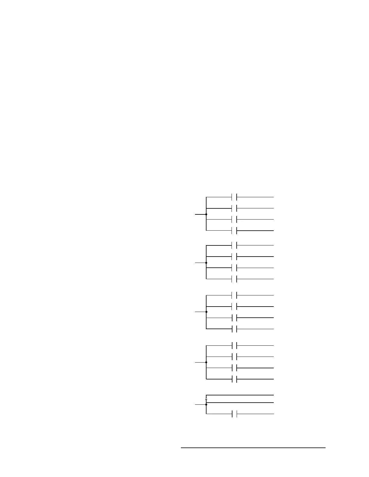
See the Unit Wiring diagram and Figure 40 on page
160. The digital outputs are located on TB7, TB8, and
TB9 and TB-10 of the microboard. ALL OUTPUTS
ARE 120VAC with the exception of TB8-6 to TB8-7
which are the contacts that can be used for a remote
evaporator pump start signal. The voltage applied to
either of these terminals would be determined by field
wiring.
Each output is controlled by the microprocessor by
switching 120VAC to the respective output connection
energizing contactors, evaporator heater, and solenoids
according to the operating sequence (see Figure 40 on
page 160).
120VAC is supplied to the I/O board via connections
at TB7-1, TB7-6, TB10-1, TB10-6, TB8-1 and TB9-1.
Figure 40 on page 160 illustrates the relay contact
architecture on the microboard.
FIGURE 40 - I/O BOARD RELAY CONTACT
ARCHITECTURE
LD12722A
SYS 1
COMP 1
TB7-2
SYS 1
COMP 2
TB7-4
SYS 1
COMP 3
TB7-5
TB7-3 LLSV 1
TB8-6
EVAP
PUMP
TB8-7
TB7
SYS 2
HGSV
TB10-7
TB10-8
TB10-9
TB10-10
TB10
TB8
TB10
SYS 2
COMPR 1 (4)
TB10-2
LLSV 2
TB10-3
SYS 2
COMPR 2 (5)
TB10-4
SYS 2
COMPR 3 (6)
TB10-5
TB7
TB7-7
TB7-9
TB7-10
TB7-8
TB8-2
HEAT EXCH
HEATER