FORM QWC3-NM1
ISSUE DATE: 11/20/2020
SECTION 8 – UNIT OPERATION
QUANTECH
148
RETURN CHILLED LIQUID SYSTEM LEAD/
LAG AND COMPRESSOR SEQUENCING
A lead/Lag option may be selected to help equalize
average run hours between systems with 2 refriger-
ant systems. This may be programmed under the OP-
TIONS key. Auto Lead/Lag of the 2 systems based on
average run hours of the compressors in each system.
Manual Lead/Lag selects specifically the sequence
which the microprocessor starts the systems.
The microprocessor will sequence compressors load
and unload systems according to Table 16 on page
148. The microprocessor will lead/lag compressors
within each circuit to maximize individual compres-
sor run time for the purpose of lubrication. It will also
prevent the same compressor from starting 2 times in
a row. The microprocessor will not attempt to equalize
run time on individual compressors within a system.
Each compressor in a system will be assigned an ar-
bitrary number 1, or 2. The non-running compressor
within a system with the lowest priority number will
always be the next compressor to start. The running
compressor with priority number 1 will always be the
next compressor to shut OFF. Whenever a compressor
is shut OFF, the priority numbers of all compressors
in each system will be decreased by 1 with the wrap
around. This control scheme assures the same com-
pressor does not repeatedly cycle ON and OFF.
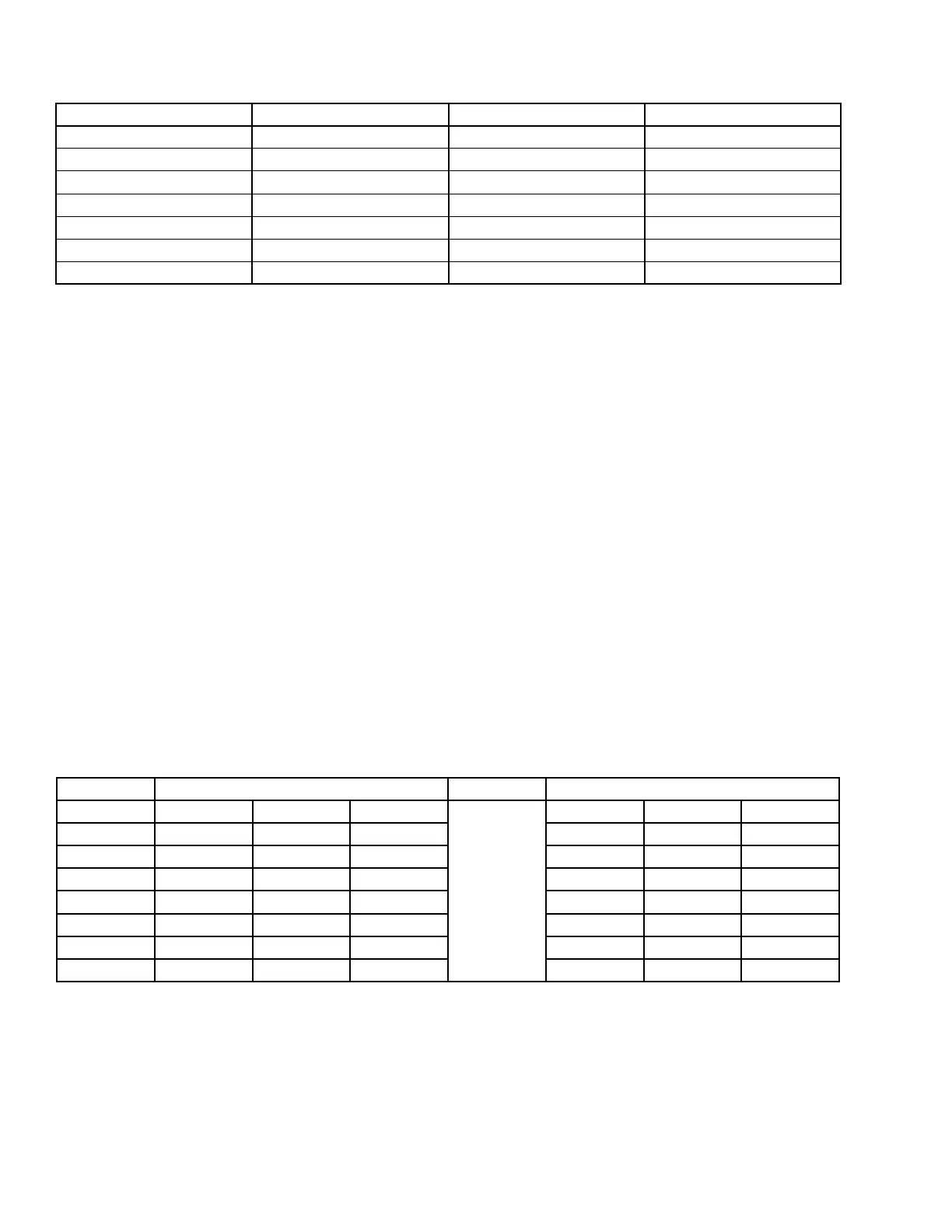
TABLE 15 - RETURN CHILLED LIQUID CONTROL FOR 4 COMPRESSORS (6 STEPS)
*STEP COMPRESSOR COMPRESSOR ON POINT COMPRESSOR OFF POINT
0 0 SETPOINT SETPOINT
1 1 W/HGB SP + CR/8 (NOTE 1) SETPOINT
2 1 NO HGB SP + CR/4 SP +CR/8
3 2 SP + 2*CR/4 (NOTE 2) SP + CR/4
4 2 SP + 2*CR/4 SP + CR/4 (NOTE 3)
5 3 SP + 3*CR/4 SP + 2*CR/4
6 4 SP + CR SP + 3*CR/4
Notes:
1. Step 1 is Hot Gas Bypass and is skipped when loading occurs. Hot Gas Bypass operation is inhibited during Pumpdown.
2. Step 3 is skipped when loading occurs.
3. Step 4 is skipped when unloading occurs.
* STEP can be viewed using the OPER DATA key and scrolling to COOLING DEMAND.
TABLE 16 - RETURN CHILLED LIQUID CONTROL FOR 4 COMPRESSORS (6 STEPS)
LEAD SYSTEM LAG SYSTEM
Step COMP 1 COMP 2 - COMP 1 COMP 2 -
0 OFF OFF - OFF OFF -
1 ON + HG OFF - See NOTE 1 OFF OFF -
2 ON OFF - OFF OFF -
3 ON OFF - See NOTE 2 ON OFF -
4 ON ON - See NOTE 3 OFF OFF -
5 ON ON - ON OFF -
6 ON ON - ON ON -
NOTES
1. Step is Hot Gas Bypass and is skipped when loading occurs. Hot Gas Bypass operation is inhibited during pumpdown. For Leaving Chilled
Liquid Control the Hot Gas Bypass solenoid is energized only when the lead compressor is running and the LWT less than SP, the Hot Gas
Bypass solenoid is turned OFF when the LWT more than SP plus CR/2.
2. Step 3 is skipped when loading occurs.
3. Step 4 is skipped when unloading occurs.