FORM QWC3-NM1
ISSUE DATE: 11/20/2020
SECTION 5 – TECHNICAL DATA
QUANTECH
84
FOR 5 & 6 COMPR.
UNITS
JUMPER REQD. FOR 4
COMPR. UNITS
JUMPER REQD. FOR 4
& 5 COMPR. UNITS
FOR 6 COMPR.
UNITS ONLY.
035-21499-103 REV. F
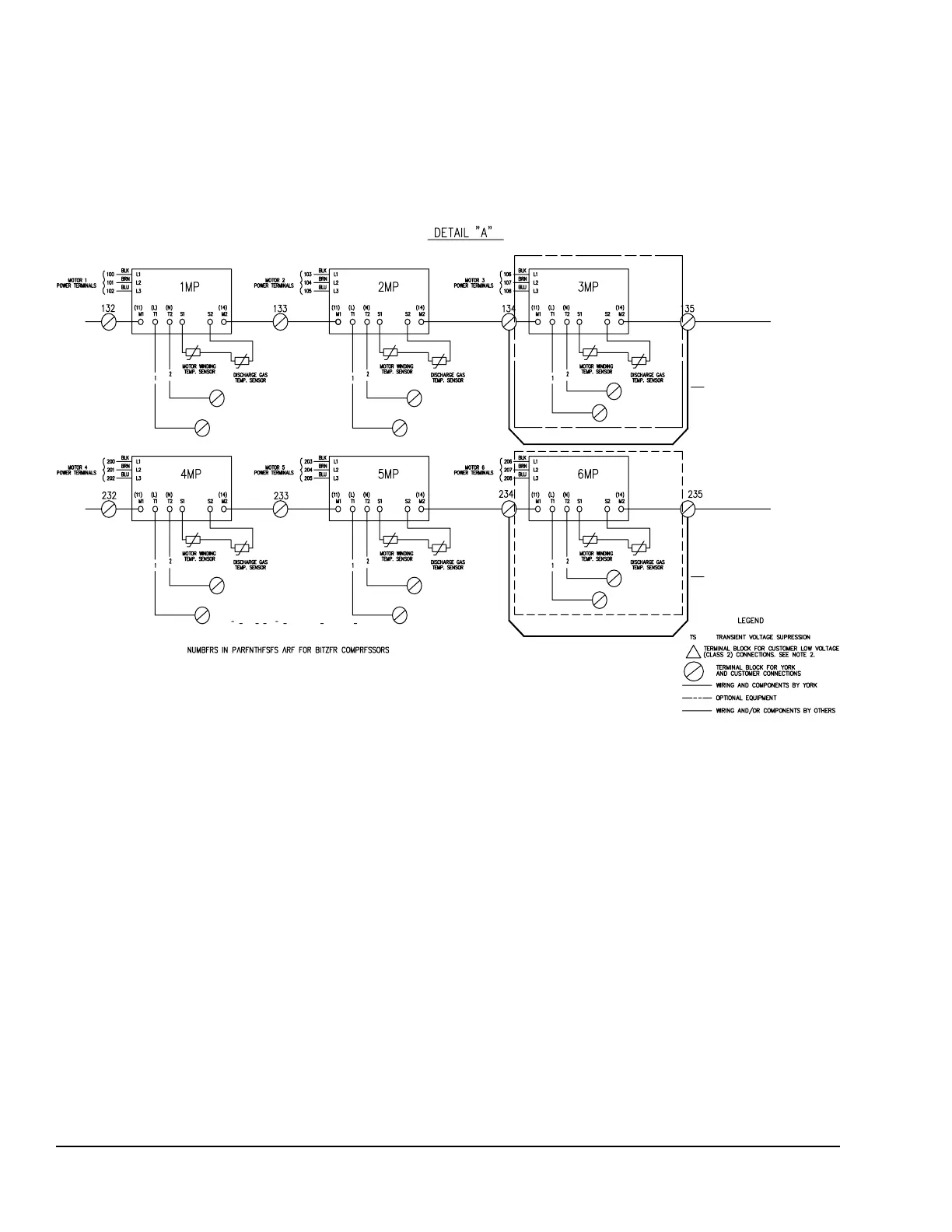
FIGURE 33 - ELEMENTARY WIRING DIAGRAM DETAILS, 5 AND 6 COMPRESSOR
ELEMENTARY WIRING DIAGRAM DETAILS
QWC3100T, 115T, 150T, 170T and 200T STANDARD EFFICIENCY UNITS
QWC3095T, 0130T and 150T HIGH EFFICIENCY UNITS
Notes:
1. Field wiring to be in accordance with the current edition of the National Electrical Code as well as all other applicable codes and speci-
cations
2. Contacts must be suitable for switching 24VDC, (gold contacts recommended).Wiring shall not be run in the same conduit with any line
voltage (class 1) wiring.
3. To cycle unit ON and OFF automatically with contact shown, install a cycling device in series with the ow switch. See note 2 for contact
rating and wiring specications.
4. To stop unit (emergency stop) with contacts other than those shown, install the stop contact between terminals 5 and 1. If a stop device
is not installed, a jumper must be connected between terminals 5 and 1. Device must have a minimum contact rating of 6A at 115VAC.
5. Contacts are rated at 115V, 100VA, resistive load only, and must be suppressed at load by user.
6. Optional current readout. 5V = 200A.
7. 1MP thru 6MP are contained in their respective compressor junction boxes.
LD26944