SECTION 9 – SERVICE AND TROUBLESHOOTING
FORM QWC3-NM1
ISSUE DATE:11/20/2020
QUANTECH
159
9
Analog Inputs – Pressure
See the Elementary Wiring Diagram on page 66.
Pressure inputs are connected to the microboard on
plugs J7 and J9. These analog inputs represent vary-
ing DC signals corresponding to varying pressures. All
voltages are in reference to the unit case (ground).
System 1 discharge and suction pressures will be con-
nected to J7 of the microboard. System 2 discharge and
suction pressure transducers will be connected to J9 of
the microboard.
The discharge transducers are optional on all units. If
the discharge transducers are not installed, no connec-
tions are made to the microboard and the discharge
pressure readout on the display would be zero.
The suction pressure transducers are standard on all
QWC chillers. The suction pressure transducers have a
range of 0 to 400 PSIG. The output will be linear from
0.5VDC to 4.5VDC over the 400 PSIG (27.5 barg)
range.
The discharge transducers have a range from 0 to
650 PSIG. The output will be linear from 0.5VDC to
4.5VDC over the 650 PSIG (41.25 barg) range. Fol-
lowing is the formula that can be used to verify the
voltage output of the transducer. All voltage readings
are in reference to ground (unit case).
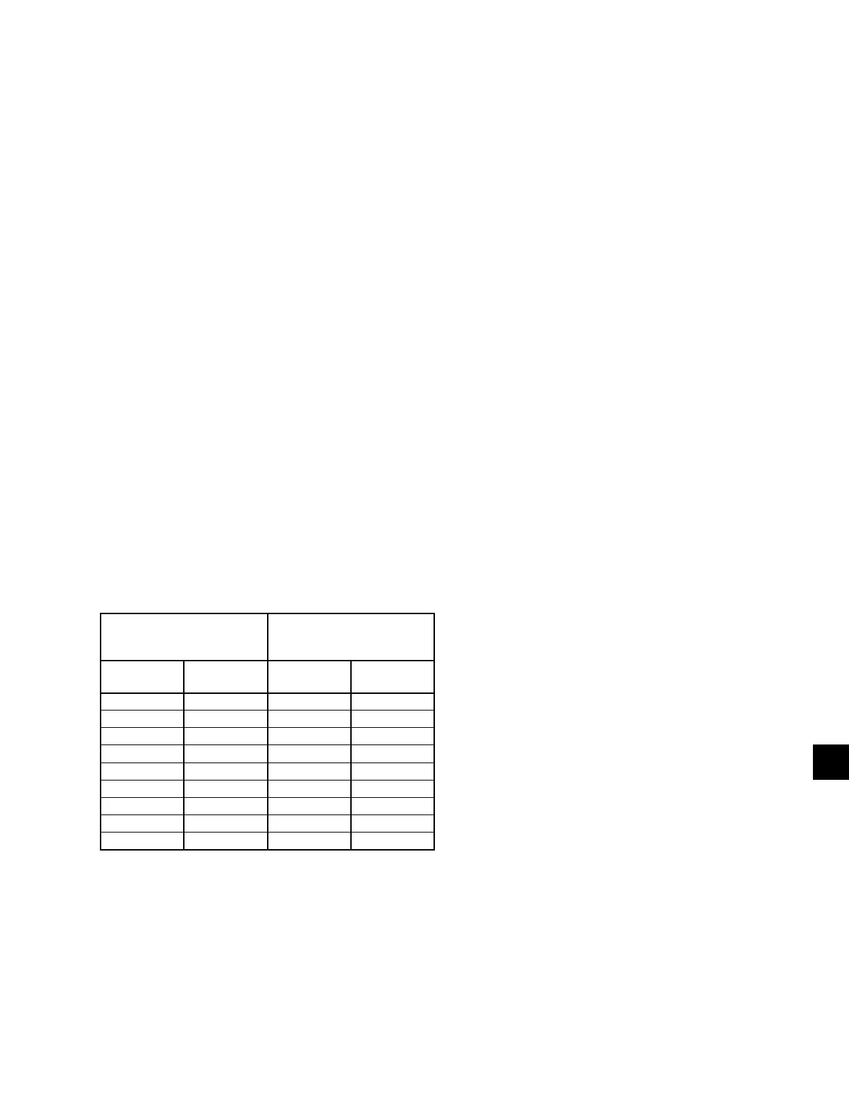
TABLE 23 - PRESSURE TRANSDUCERS
0-400 PSIG SUCTION
PRESSURE
TRANSDUCER
0-650 PSIG DISCHARGE
PRESSURE
TRANSDUCER
PRESSURE
PSIG
VOLTAGE
VDC
PRESSURE
PSIG
VOLTAGE
VDC
0 0.5 0 0.5
50 1.0 81.25 1.0
100 1.5 162.5 1.5
150 2.0 243.75 2.0
200 2.5 325 2.5
250 3.0 406.25 3.0
300 3.5 487.75 3.5
350 4.0 568.75 4.0
400 4.5 650 4.5
Red Wire = 5V, Black wire = 0V, White/Green Wire = signal
TEST POINTS:
Suction Pressure:
System 1:
...............................................
Microboard J7-10 to J7-9
System 2:
...............................................
Microboard J9-10 to J9-9
Discharge Pressure:
System 1:
...............................................
Microboard J7-11 to J7-7
System 2:
...............................................
Microboard J9-11 to J9-7
V = (Pressure in PSIG x .01) + .5
or
V = (Pressure in barg x .145) + .5
where V = DC voltage output
Pressure = pressure sensed by transducer
The I/O board connections for the Discharge
Transducers:
System 1 Discharge Transducer
J7-6 = +5VDC regulated supply to transducer.
J7-11 = VDC input signal to the microboard. See the
formula above for voltage readings that cor-
respond to specific discharge pressures.
J7-7 = +5VDC return.
J7-2 = drain (shield connection = 0VDC).
System 2 Discharge Transducer
J9-6 = +5VDC regulated supply to transducer.
J9-11 = VDC input signal to the microboard. See the
formula above for voltage readings that cor-
respond to specific discharge pressures.
J9-7 = +5VDC return.
J9-2 = drain (shield connection = 0VDC).