FORM QWC3-NM1
ISSUE DATE: 11/20/2020
SECTION 4 – INSTALLATION
QUANTECH
36
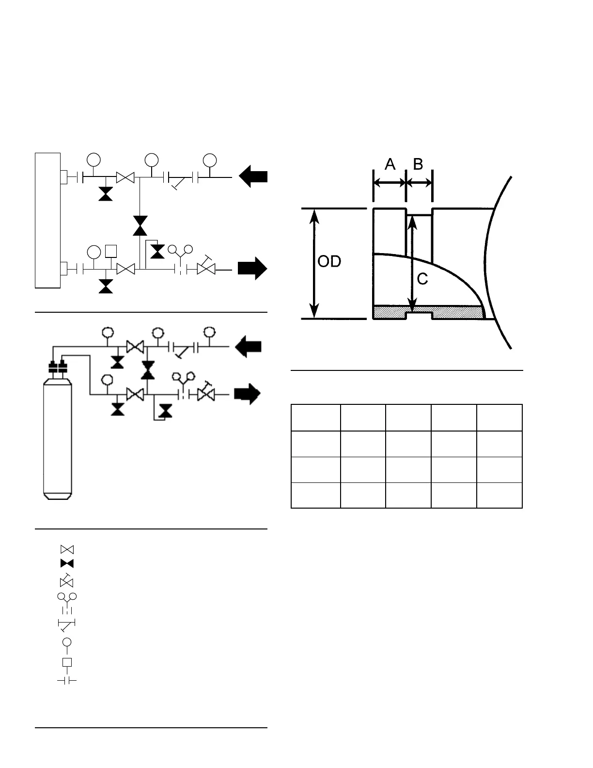
PIPEWORK ARRANGEMENT
The following are suggested pipework arrangements
for single unit installations, for multiple unit installa-
tions, each unit should be piped as shown in Figure 12
on page 36 and Figure 13 on page 36. Recom-
mendations of the Building Services Research As-
sociation.
LD06596
FIGURE 12 - CHILLED LIQUID SYSTEM
LD06598
FIGURE 13 - CONDENSER COOLING LIQUID
SYSTEM
FIGURE 14 - PIPEWORK ARRANGEMENTS
LEGEND
LD06597A
ISOLATING VALVE - NORMALLY OPEN
ISOLATING VALVE - NORMALLY CLOSED
FLOW REGULATING VALVE
FLOW MEASUREMENT DEVICE
STRAINER
PRESSURE TAPPING
FLOW SWITCH
FLANGED CONNECTION
Isolating Valve - Normally Open
Isolating Valve - Normally Closed
Flow Regulating Valve
Flow Measurement Device
Strainer
Flow Switch
Flanged Connection
PRESSURE TAPPING
CONNECTION TYPES AND SIZES
For connection sizes relevant to individual models, see
SECTION 9 – SERVICE AND TROUBLESHOOTING.
Cooler Connections
Standard chilled and condenser cooling liquid connec-
tions are of the ANSI/AWWA C-606 groove type.
LD06601
FIGURE 15 - COOLER CONNECTIONS
TABLE 2 - CONDENSER / COOLER CONNECTIONS
NOMINAL
SIZE
OD A B C
8” 8-5/8”
3/4
±1/32”
7/16
±1/32”
8.416”
6” 6-5/8”
5/8
±1/32”
3/8
±1/32”
6.433”
5” 5-9/16”
5/8
±1/32”
3/8 1/32” 5.395