Part Replacement Replacing a Load Cell
CubiScan 25 Service Manual 47
20. Remove the damaged load cell body and the attached
load cell cable.
21. Route the new load cell cable into place, using the
same route observed in step 18.
22. Use zip ties to secure the load cell cable in place.
When you are finished, move the CubiScan 25 back
to its upright position.
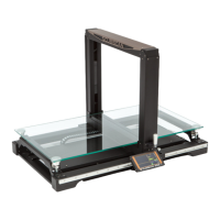
23. Replace the four load cell balls from step 14.
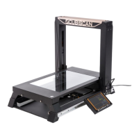
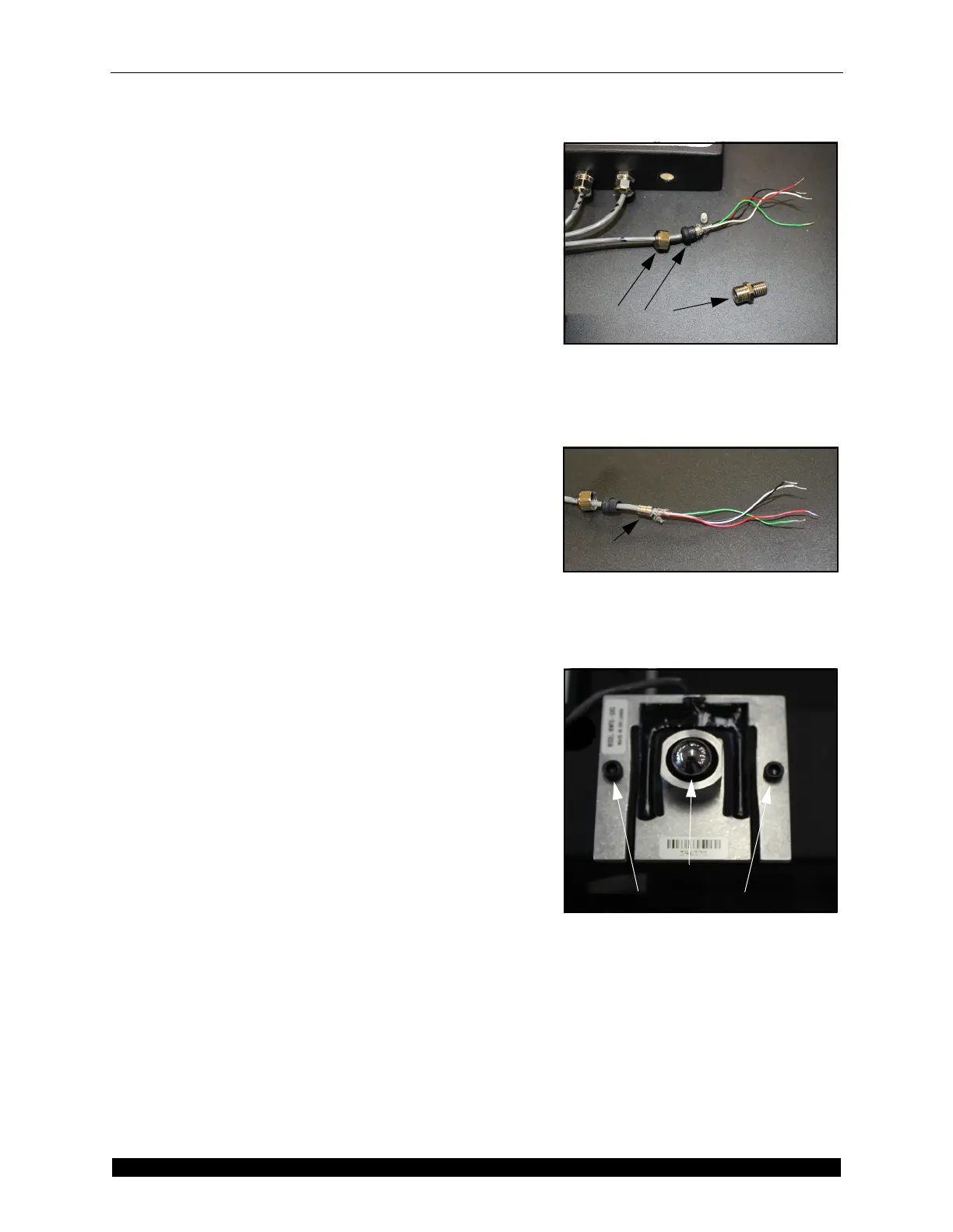
24. Use the metal attachments from step 13 and attach
them to the new load cell cable. Refer to Figure 68
and Figure 69.
25. Route the new load cell cable into the load cell
summing box and secure it using the nut from step
12.
26. Snap the ferrite from step 11 into place.
27. Move the gate to the left side and replace the shroud.
Secure it using the screws and nuts from steps 7 and
8. Move the gate back into the home position.
28. Reconnect the load cell connection wires. Refer to
Figure 65.
29. Replace the load cell summing box lid and secure it
using the screws from step 5.
30. Replace the scale plate and secure it using the thumb
screws from step 3. The thumb screws should not be
tightened all the way, they should merely hold the
scale plate in place while still allowing free
movement.
31. Replace the glass platform.
32. Power the CubiScan 25 on.
33. When you have finished replacing the load cell the
load cells will need to be balanced. For instructions
on balancing the load cells, see “Balancing the Load
Cells” on page 23.
34. Calibrate the CubiScan 25. For calibration
instructions, see “Scale Calibration” on page 13.
Figure 68
Load Cell Cable Attachments
Figure 69
Metal Attachments
Figure 70
Load Cell
Load Cell Ball
Load Cell Screws