INTRODUCTION
APPENDIX B
TRACK
FORMATTING
The ProDrive disk drives are shipped from the factory as "hard sectored" drives. That is, all physical
sector addresses are written on the disks before the drives are shipped. Sector size and number
of
sectors per
track are, therefore, not user selectable. The SCSI peripheral bus uses "logical blocks" as the means
of
transferring data to and from the disk drives. This appendix describes the physical fonnat
of
the ProDrive
as it is defined
at
the factory prior to shipment.
TRACK FORMAT
The ProDrive Series drives use information on the disks to define the physical sectors. Each sector is
capable
of
holding 512 bytes
of
data (plus 6 bytes for ECC). Tracks 0 to 589 contain 35 sectors; tracks
590
.to
833 contain 28 sectors. One sector is used as a spare for every 6 tracks for defect management.
(See Appendix C.) For the
ProDrive 40S (2 disks, 3 heads), the first 590 cylinders have
105
physical
sectors available and the last 243 cylinders have 84 sectors. The
ProDrive
80S
(3
disks, 6 heads) has 210
and 168 sectors available. These sectors are sequentially numbered beginning with cylinder 0, head 0
through cylinder 833, head 5 in the case
of
the ProDrive 80S;
or
cylinder 833, head 2 in the case
of
the
ProDrive 40S. Therefore, the ProDrive 40S contains 82,029 sequentially-numbered sectors, and the
ProDrive 80S contains 164,058 sequentially-numbered sectors, each capable
of
storing 512 bytes
of
data.
TRACK AND CYLINDER SKEWING
Since the ProDrive 40S/80S drives are storage subsystems with integrated SCSI controllers. the function
and design
of
the controller can be optimized specifically for the drive. One method
of
optimization
employed by Quantum to improve data throughput is skewing sector addresses. The purpose
of
track and
cylinder skewing is to minimize latency time and thus increase data throughput when data is sequentially
accessed to or from the disk. The two types
of
skewing employed, track and cylinder skewing, are described
below.
TRACK SKEWING
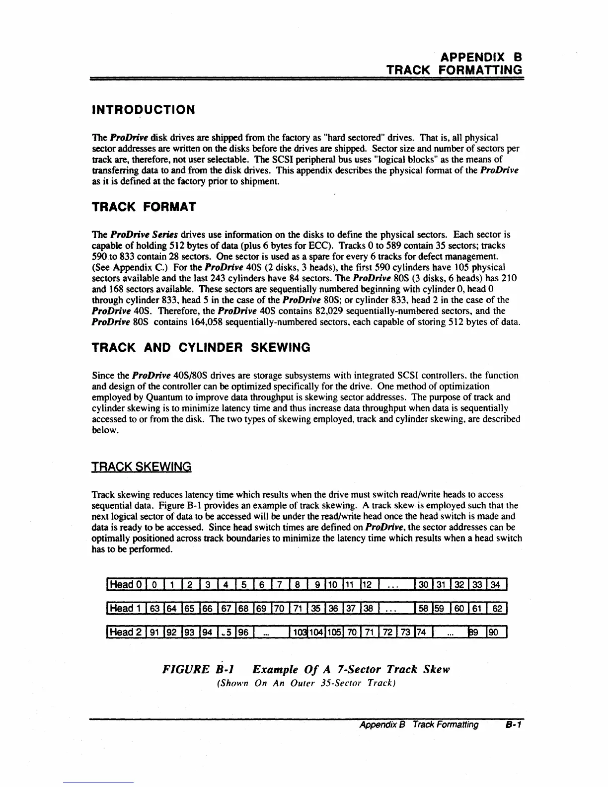
Track skewing reduces latency time which results when the drive must switch read/write heads to access
sequential data. Figure
B-1
provides an example
of
track skewing. A track skew is employed such that the
next logical sector
of
data to be accessed will
be
under the read/write head once the head switch
is
made and
data is ready to be accessed. Since head switch times are defined on
ProDrive,
the sector addresses can be
optimally positioned across
track boundaries to minimize the latency time which results when a head switch
has to be perfonned.
I
Head
0 1 0
11
1 2 1 3 I 4 I 5 I 6 I 7 I 8 1 9
110
111
112
I
158
159
160
161
1
62
I
I
Head
2191
192 193
194
1
..
5196
I
-
FIGURE
B-1
Example
Of
A 7-Sector Track
Skew
(Shown On
An
Outer
35-Sector Track)
Appendix B
Track
Formatting
8-1