Section 4
SCSI
Interface
4.3.2
SCSI ELECTRICAL CHARACTERISTICS
All signals are low true and use open collector drivers tetminated with 220 ohms to +5 volts (nominal) and
330 ohms to ground at each end
of
the cable. Resistor networks
in
sockets are provided on the ProDrive
to terminate the lines.
NOTE:
If
multiple devices will be connected to the SCSI bus, terminators should be removed
in
all but
the two devices at the cable ends.
See Section 2.4
of
this manual for the location
of
terminators
on the drive.
Each signal driven by the
ProDrive has the following output characteristics:
• True (Signal Assertion) = 0.0 to 0.5 Vdc at 48 rnA (max)
• False (Signal Non-Assertion) = 2.5 to 5.25 Vdc
Each signal from the host to the
ProDrive must have the following characteristics (measured at the drive):
• True (Signal Assertion) = 0.0 to 0.8 V dc
• False (Signal Non-Assertion) = 2.5 to 5.25 Vdc
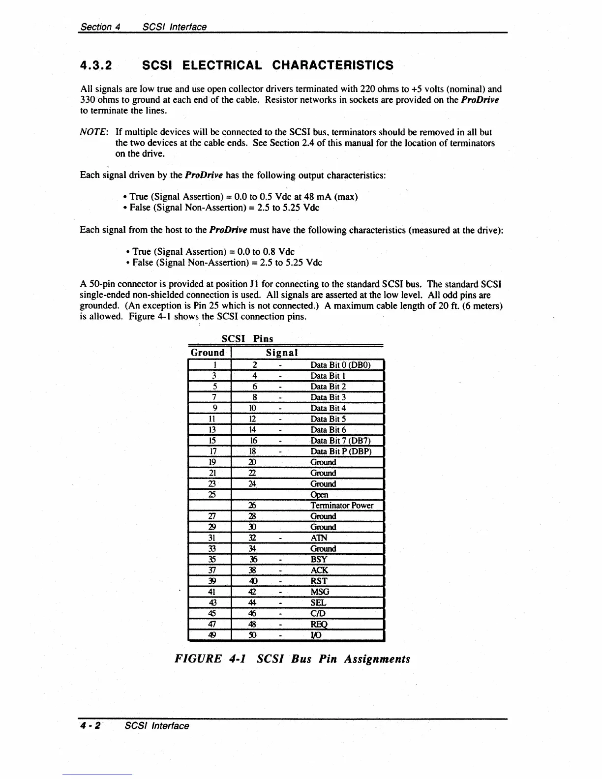
A
50-pin connector is provided at position J 1 for connecting to the standard SCSI bus. The standard SCSI
single-ended non-shielded connection is used. All signals are asserted at the low level. All odd pins are
grounded. (An exception is
Pin 25 which
is
not connected.) A maximum cable length
of
20 ft. (6 meters)
is allowed. Figure 4-1 shows the SCSI connection pins.
SCSI
Pins
Ground I
Signal
1 2
-
Data
Bit
0
(DBO)
3 4
-
Data
Bit
1
5 6
-
Data
Bit
2
7
8
-
Data
Bit
3
9
10
-
Data
Bit4
11
12
-
Data Bit 5
13
14
-
Data Bit 6
15
16
-
Data Bit 7 (DB7)
17 18
-
Data Bit P (DBP)
19
a>
Ground
21
22
Ground
Z3
24
Ground
25
Open
~
Tenninator Power
Zl
28
Ground
~
:l)
Ground
31
32
-
AlN
33
34
Ground
35
?6
-
BSY
J7
38
-
ACK
~
«>
-
RST
41
42
-
MSG
43
44
-
SEL
45
46
-
C/O
if!
48
-
REQ
49
~
-
to
FIGURE 4-1
SCSI
Bus
Pin Assignments
4 - 2
SCSI
Interface