5.9.2
Section 5
SCSI Programming Guidelines
LOGICAL
BLOCK
ADDRESS
RANGES
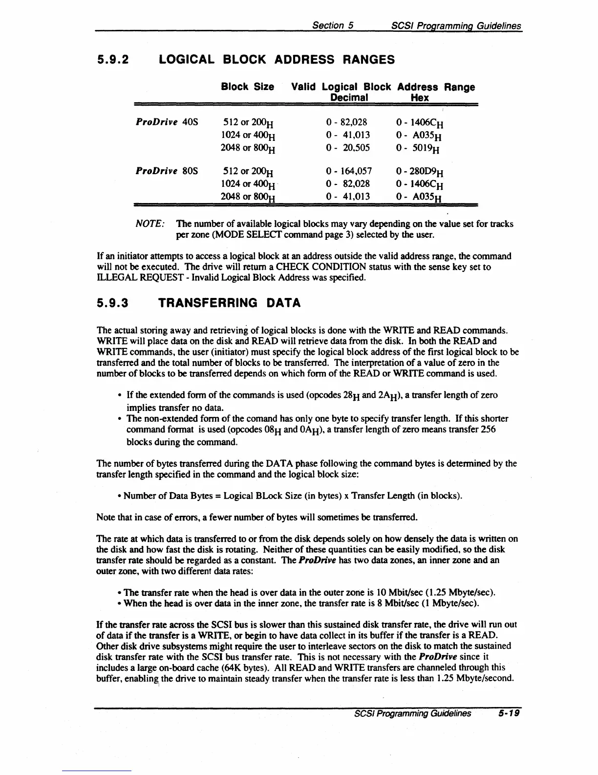
Block Size Valid Logical Block Address Range
Decimal Hex
ProD
rive
40S
512 or 200H
0-82,028
0-
1406CH
10240r4~
0-
41,013
0-
A035H
2048
or 800H
0-
20.505
0-
5019H
ProD
rive
80S
512
or
200H
0-
164,057
0-
280D9H
10240r~·
0-
82,028
0-
1406CH
2048
or8~
0-
41,013
0-
A035H
NOTE: The number
of
available logical blocks may vary depending on the value set for tracks
per
zone (MODE
SELECf
command page 3) selected by the user.
If
an initiator attempts to access a logical block at an address outside the valid address range, the command
will not be executed. The drive will return a CHECK
CONDITION status with the sense key set
to
ILLEGAL REQUEST - Invalid Logical Block Address was specified.
5.9.3
TRANSFERRING
DATA
The actual storing away and retrieving
of
logical blocks is done with the WRITE and READ commands.
WRITE will place data
on
the disk and READ will retrieve data from the disk. In both the READ and
WRITE commands, the user (initiator) must specify the logical block address
of
the first logical block to be
transferred and the total number
of
blocks to be transferred. The interpretation
of
a value
of
zero in the
number
of
blocks to be transferred depends on which form
of
the READ
or
WRITE command is used.
•
If
the extended form
of
the commands is used (opcodes 28H and 2AH), a transfer length
of
zero
implies transfer no data.
• The non-extended form
of
the comand has only one byte to specify transfer length.
If
this shorter
command format is used (opcodes
08H and OAH), a transfer length
of
zero means transfer 256
blocks during the command.
The number
of
bytes transferred during the DATA phase following the command bytes is determined by the
transfer length specified in the command and the logical block size:
• Number
of
Data Bytes = Logical BLock Size (in bytes) x Transfer Length (in blocks).
Note that in case
of
errors, a fewer number
of
bytes will sometimes be transferred.
The rate at which data is transferred to
or
from the disk depends solely
on
how densely the data is written on
the disk and how fast the disk is rotating. Neither
of
these quantities can be easily modified, so the disk
transfer rate should be regarded as a constant. The
ProDrive has two data zones, an inner zone and an
outer zone, with two different data rates:
• The transfer rate when the head is over data in the outer zone is 10 Mbit/sec (1.25 Mbyte/sec).
• When the head is over data in the inner zone, the transfer rate is 8 Mbit/sec
(1
Mbyte/sec).
If
the transfer rate across the SCSI bus is slower than this sustained disk transfer rate, the drive will run out
of
data
if
the transfer is a WRITE,
or
begin to have data collect in its buffer
if
the transfer is a READ.
Other disk drive subsystems might require the user to interleave sectors on the disk to match the sustained
disk transfer rate with the SCSI bus transfer rate. This is not necessary with the
ProDrive since it
includes a large on-board cache (64K bytes). All READ and WRITE transfers are channeled through this
buffer, enabling: the drive to maintain steady transfer when the transfer rate is less than 1.25 Mbyte/second.
SCSI Programming Guidelines 5
·19