Section 3 Principles of Operation
3.2
ProDrive
40S/80S DRIVE ELECTRONICS
3.2.1
GENERAL DESCRIPTION
All drive electronics, including SCSI controller functions, are contained on one Printed Circuit Board
Assembly (PCBA). This is accomplished through advanced circuit design and the use
of
miniature surface-
mounted devices and proprietary
VLSI components. The only electrical components not contained on the
PCBA are the preamplifier chip for the read/write circuitry, and the electronic circuitry for the optical
encoder photocells and infared LED; these are located under the drive cover. The preamplifier is mounted as
close to the read/write heads as possible to improve the signal-to-noise ratio. The following paragraphs
provide operation details for major functional
circui~s
within the drive.
3.2.2
HEAD POSITIONING SYSTEM
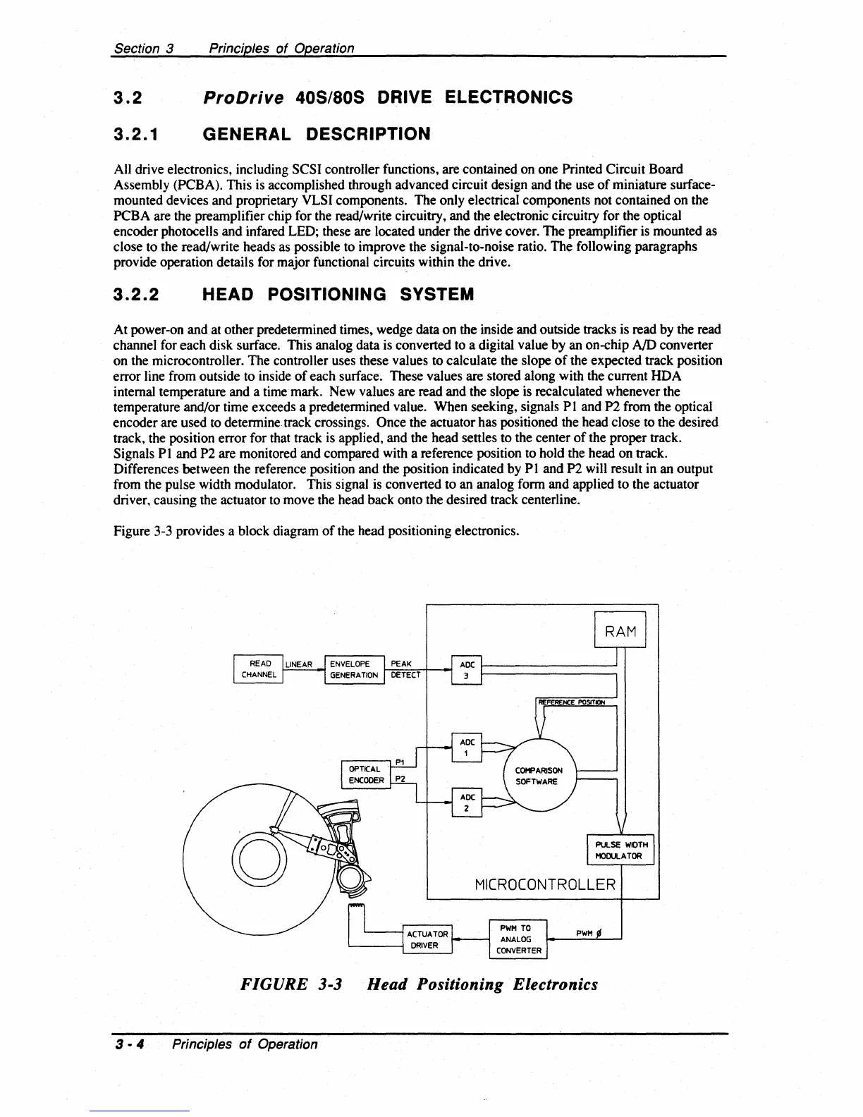
At power-on and at other predetermined times, wedge data on the inside and outside tracks is read by the read
channel for each disk surface. This analog data is converted to a digital value by an on-chip
AID
converter
on the microcontroller. The controller uses these values to calculate the slope
of
the expected track position
error line from outside to inside
of
each surface. These values are stored along with the current HDA
internal temperature and a time mark. New values are read and the slope
is
recalculated whenever the
temperature and/or time exceeds a predetermined value. When seeking, signals P I and P2 from the optical
encoder are used to determine track crossings.
Once the actuator has positioned the head close to the desired
track, the position error for that track is applied, and the head settles to the center
of
the proper track.
Signals
PI
and P2 are monitored and compared with a reference position to hold the head on track.
Differences between the reference position and the position indicated by
PI
and P2 will result in an output
from the pulse width modulator. This signal is converted to an analog form and applied to the actuator
driver, causing the actuator to move the head back onto the desired track centerline.
Figure 3-3 provides a block diagram
of
the head positioning electronics.
MICROCONTROLLER
FIGURE
3-3
Head Positioning Electronics
3 • 4 PrinCiples
of
Operation