Section 2
Installation and Operation
2.1.3
MOUNTING
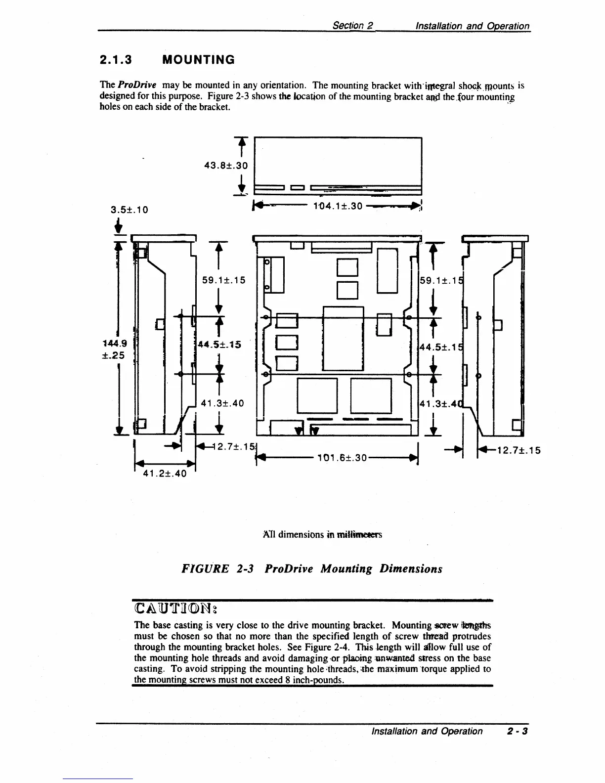
The ProDrive may be mounted in any orientation. The mounting bracket with'integral
shoc.J<.mo
unts
is
designed for this purpose. Figure 2-3 shows
the location
of
the mounting bracket
ami
the .four mountin,g
holes on each side
of
the bracket.
'.
T
D
o
1'04.1
±.30
---,..
••
;:
D
D
DD
2.7±.1~
'01'6±'30
__
~
...
ll
~
All dimensions
in
millimeters
FIGURE 2-3 ProDrive Mounting Dimensions
The base casting is very close to the drive mounting bracket. Mounting
:9OF.ew
!kmg:ths
must be chosen so that
no
more than the specified length
of
screw
thread
protrudes
through the mounting bracket holes.
See Figure 2-4. This .length will allow full use
of
the mounting hole threads and avoid damaging ,orplaoing
:unw.ante.d
stress on the base
casting.
To
avoid stripping the mounting hole ;ihreads,
;themaximum
'torque applied to
the mounting screws must not exceed 8 inch-pounds.
Installation and Operation 2 • 3