Section 2
Installation and Operation
2.3
INTERCONNECTING
CABLE
CONNECTORS
2.3.1
DC POWER CONNECTOR
The DC power connector (J2)
is
a 4-pin DuPont Connector (SK 20055-(00) mounted on the back edge
of
the PCB near the SCSI connector. See Figure 2-5. The recommended mating connector (P2) (AMP PIN
1-
480424-0) utilizes AMP pins [PIN 350078-4 (strip) or PIN 61173-4 (loose piece)]. J2 pins are labeled on
the J2 connector.
Pin I +12 volts DC
Pin 2 +
12
volt return (ground)
Pin 3 +5 volt return (ground)
Pin 4 +5 volts DC
NOTE: Pins 2 and 3 are connected on the drive.
FIGURE
2-5 DC Power Connector (12)
2.3.2
SCSI CONNECTOR
One SCSI cable connector
(JI)
is required for the ProDrive. Details
of
the signals required can be found
in
Section 4 - SCSI Interface.
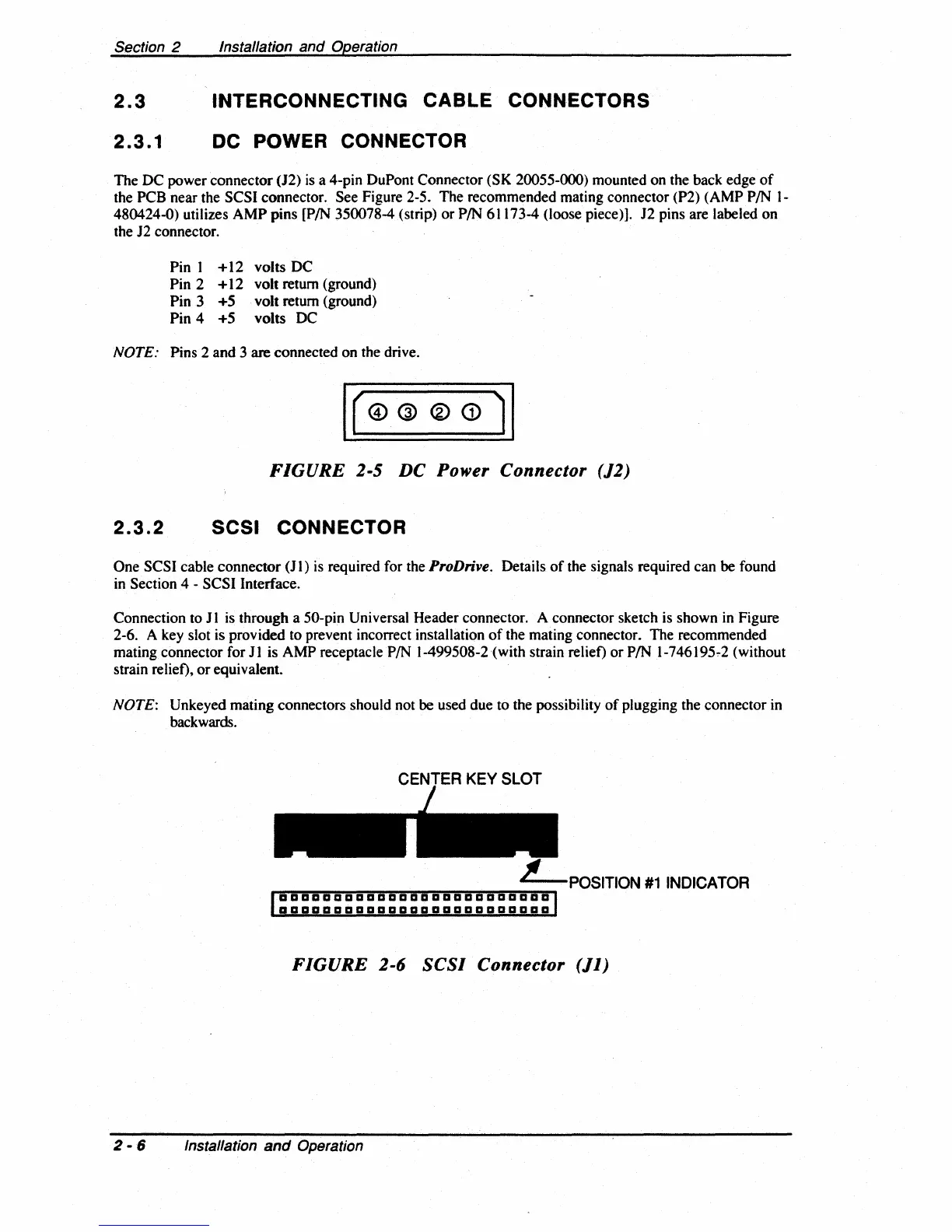
Connection to
11
is
through a 50-pin Universal Header connector. A connector sketch is shown
in
Figure
2-6. A key slot is provided to prevent incorrect installation
of
the mating connector. The recommended
mating connector for
11
is AMP receptacle
PIN
1-499508-2 (with strain relief) or PIN
1-746195~2
(without
strain relief),
or
equivalent.
NOTE: Un keyed mating connectors should not be used due to the possibility
of
plugging the connector
in
backwards.
~~~~",=""="~~=-=-=~~",=,,,,=,,"',=,,-,=,,,,-POSITION
#1
INDICATOR
aaaaaaaaaaaaaaaaaaaaaaaaa
aaaaaaaaaaaaaaaaaaaaaaaaa
FIGURE
2-6
SCSI
Connector
(11)
2 - 6 Installation
and
Operation