Section 5
SCSI
Programming Guidelines
5.11.13.4 Rigid Disk Driye Geometry Parameters. page Code
4J:l
Bit
7
I
6
5
I
4
I
3
I
2
1
1
I
0
Byte
0
RESERVED
= 0
PAGE
CODE
=
4H
1
PAGE
LENGTH
=
12H
2
(MSB)
NUMBER
OF
CYLINDERS
= 0
3
NUMBER
OF
CYLINDERS
=
3H
4
NUMBER
OF
CYLINDERS
= 42H
(lSB)
5
NUMBER
OF
HEADS
(3H
or
6
H)
6--8
(MSB)
STARTING
CYLINDER
-
WRITE
PRECOMPENSATION
= 0
(lSB)
9
(MSB)
STARTING
CYLINDER
-
REDUCED
WRITE
CURRENT
= 0
10
STARTING
CYLINDER -
REDUCED
WRITE
CURRENT =
02H
11
STARTING
CYLINDER
-
REDUCED
WRITE
CURRENT
=
4EH
(LSB)
12-13
(MSB)
DRIVE
STEP
RATE
(LSB)
14-16
(MSB)
LANDING
ZONE
CYLINDER
= 0
(LSB)
17-19
RESERVED
= 0
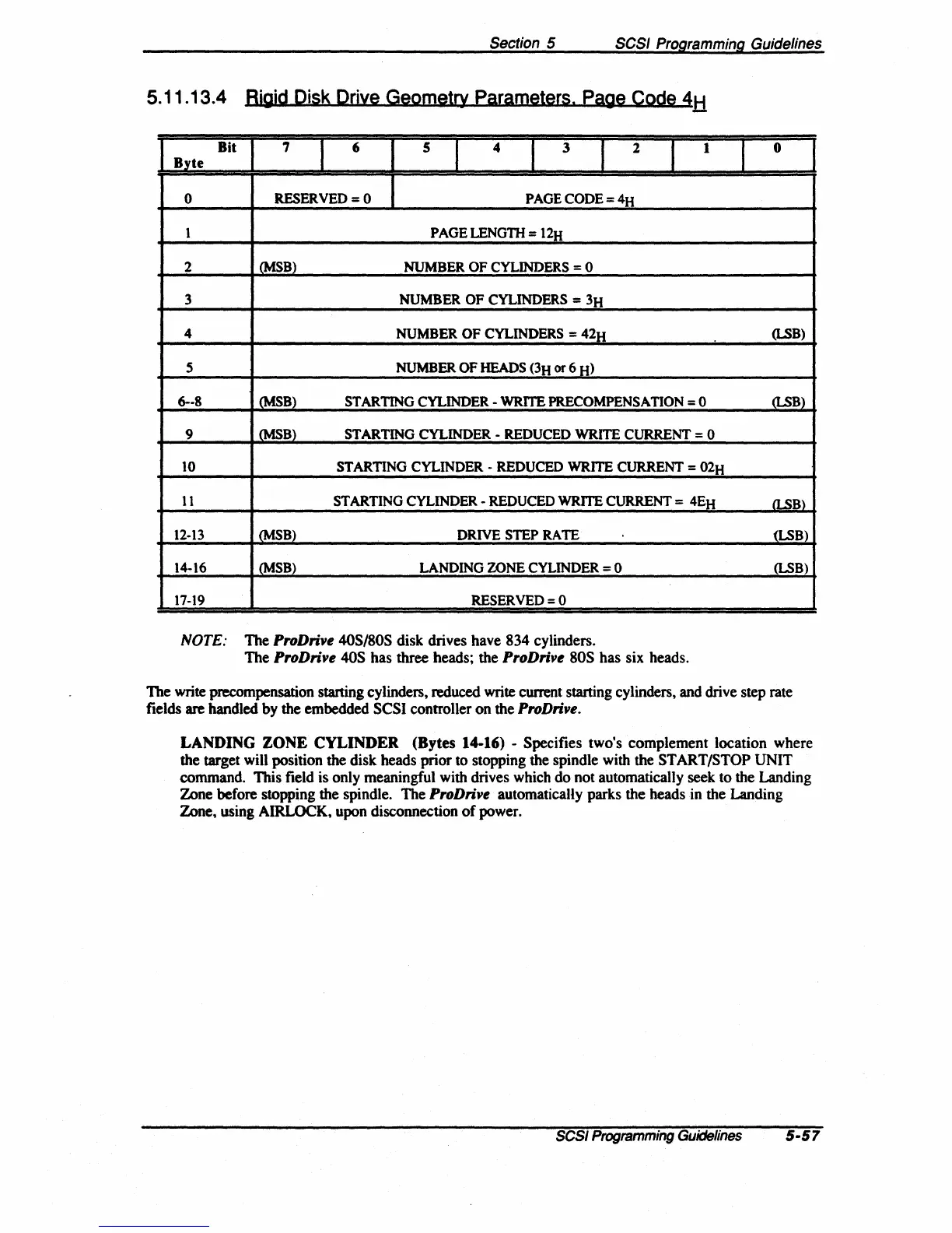
NOTE:
The ProDrive 4OS/80S disk drives have 834 cylinders.
The
ProDrive 40S has three heads; the ProDrive 80S has six heads.
The write precompensation starting cylinders, reduced write
current starting cylinders, and drive step rate
fields
are handled by the embedded SCSI controller on the
ProDrive.
LANDING ZONE CYLINDER (Bytes 14-16) - Specifies two's complement location where
the target will position the disk heads prior to stopping the spindle with the START/STOP
UNIT
command. This field is only meaningful with drives which do not automatically seek to the Landing
Zone before stopping the spindle. The
ProDrive automatically parks the heads in the Landing
Zone, using AIRLOCK, upon disconnection
of
power.
SCSI Programming Guidelines
5-57