Installation
Intelligent Electric Vehicle Chargepoints QUBEVSM-V01-R0 Installation and Operation Manual
Page 19 of 42 February 2023
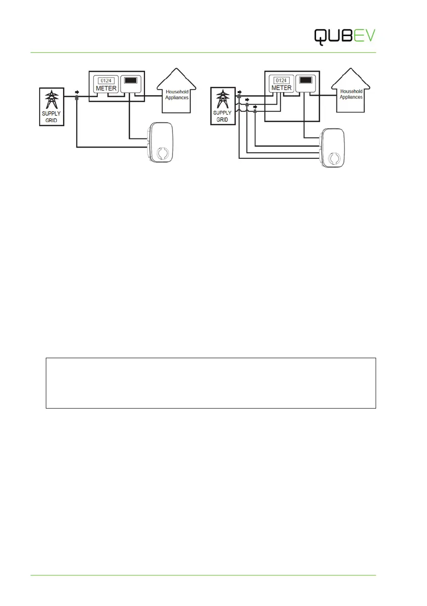
Figure 10 Single-Phase System CT Clamp Positioning Figure 11 three-Phase System CT Clamp Positioning
Connect a 3-Phase CT to the Property
3-Phase electrical supplies have 3x Live cables (L1, L2 & L3).
This means that for a 3-phase system where load balancing is required, a CT clamp must be
installed around each one of L1, L2 and L3.
Unlike a 1-phase system, connecting the CTs to the neutral cable will not allow the system to
function correctly as there are 3 CTs and only 1 Neutral cable.
1. Connect a CT cable clamps to each of L1, L2 and L3 as illustrated above.
Extend the CT Cable
If required, a CT cable may be extended up to a theoretical maximum of 100m.
x To avoid interference and reduce the loss of signal, extension cables should be as short
as possible. Extensions of 20m or less are recommended.
x Extension cables must be a screened ‘Twisted Pair’. A screened twisted pair within a CAT6
computer network cable may be used.
NOTE: Twisted pairs within a CAT cable are indicated by their matching colours.
Do NOT use conductors of different colours, to extend a cable; interference may be
induced.
If extending more than one CT, use a different colour pair for each CT.

 Loading...