CV200 Dash Camera User Manual
7
Connect it to the ignition signal output slot of
fuse box
Connect it to the power source slot of fuse box
Connect it to the ground wire of your vehicle
Monitor the external switch on/off signal
Connect the addition camera for interior or rear
views
Connect to the dash camera unit
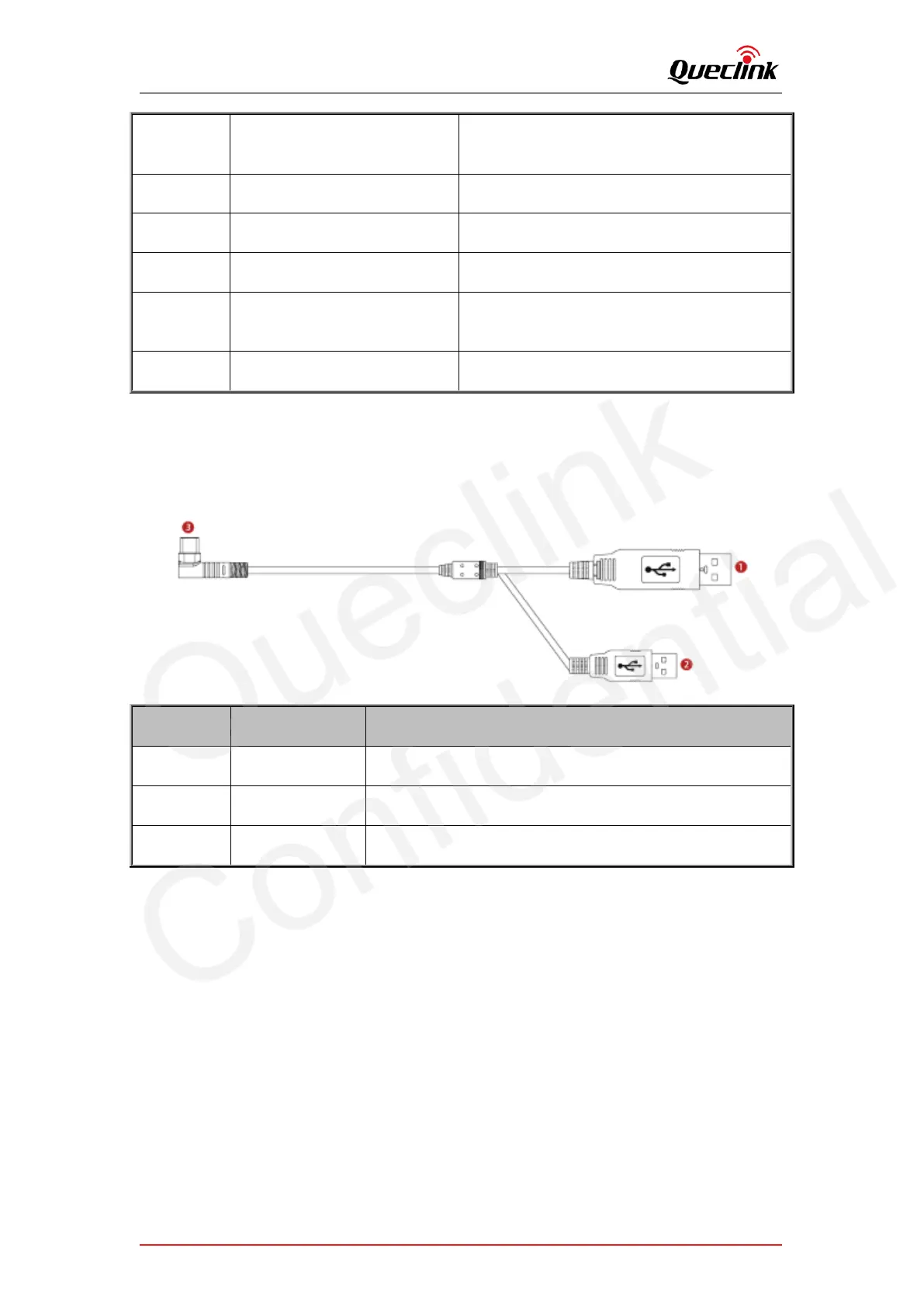
2.7. Debug cable
This 2-in-1 cable is requisite accessory provided with the product, it’s used to initialize the
configuration and debug the application by specific tools for the installers.
For parameters configuration and MCU updating
For main firmware updating
Connect to the debug port of dashcam