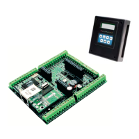
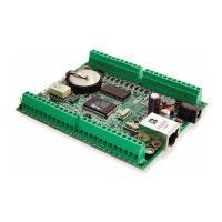
68 Smartcat (BL2100)
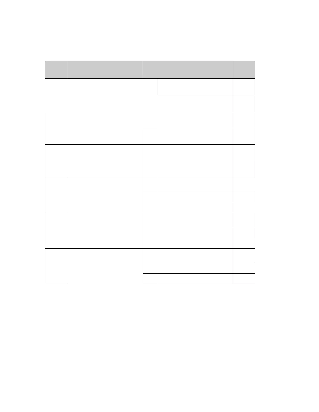
Table A-2 lists the configuration options.
Table A-2. BL2100 Jumper Configurations
Header Description Pins Connected
Factory
Default
JP1
RS-485 Bias and Termination
Resistors
1–2
5–6
Bias and termination resistors
connected
×
1–3
4–6
Bias and termination resistors not
connected
*
* Although pins 1–3 and 4–6 of header JP1 are shown “jumpered” for the termination and
bias resistors not connected, pins 3 and 4 are not actually connected to anything, and this
configuration is a “parking” configuration for the jumpers so that they will be readily
available should you need to enable the termination and bias resistors in the future.
JP2
Software I/O Configuration
Option
1–2 Standard
×
2–3
Custom (IN16–IN23 are config-
ured as digital sinking outputs)
JP3 Analog Circuit Option
1–2 Installed
BL2100
BL2120
2–3 Not installed
BL2110
BL2130
— IN00–IN07
R56 Pulled up to Vcc
×
R57 Pulled up to +K2
R54 Pulled down
— IN08–IN15
R60 Pulled up to Vcc
×
R61 Pulled up to +K2
R59 Pulled down
— IN16–IN23
R69 Pulled up to Vcc
×
R70 Pulled up to +K2
R71 Pulled down