RadioLink Electronic Limited
www.radiolink.com
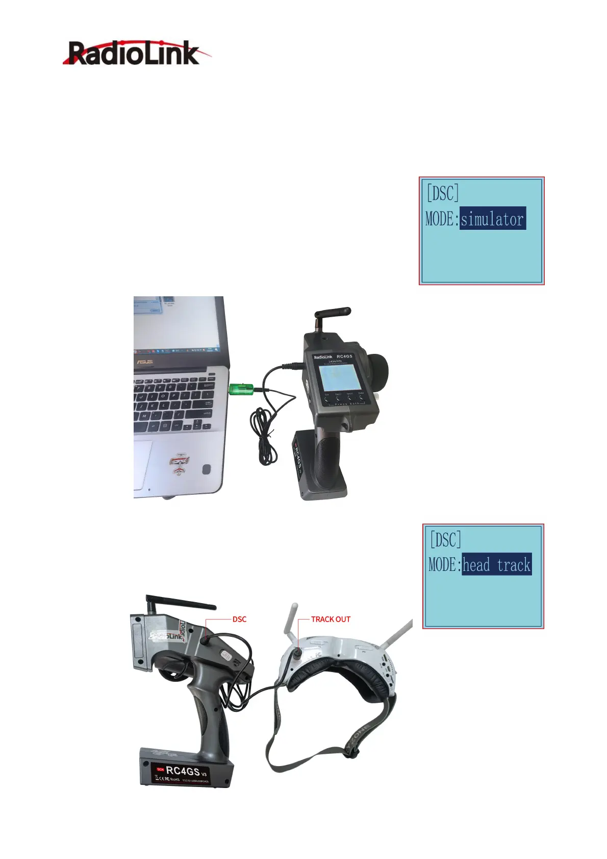
2.23 DSC port setting “DSC”
DSC is for the function of the DSC port on the left side of the transmitter. There are two modes to choose
from:
1. Simulator: Connect to the simulator or TBS Crossfire;
2. Head track: Connect to FPV goggles with head track function.
Simulator mode: If you need to connect simulator or TBS Crossfire to the DSC
port of RC4GS V3, please select the mode as: simulator. When connecting the
simulator, insert one end of the standard audio head of the simulator into the
DSC port of RC4GS V3, and follow the steps in the simulator instruction
manual to calibrate and operate the transmitter in the simulation software. The
following picture is for reference. (Please refer to the video for the method of
connecting RC4GS V3 to TBS Crossfire:
https://www.youtube.com/watch?v=6vt5QexQSQs
Head track mode: If you need to connect FPV goggles with head track function
to the DSC port of RC4GS V3, please set the mode to: head track. Then
directly insert one end of the standard audio head of the FPV goggles into the
DSC port of the remote control, and the other end into the Track Out port of the
FPV goggles.
 Loading...