Radware Alteon Installation and Maintenance Guide
Installing the Platform
Document ID: RDWR-ALOS-V2815_IG0203 39
4. Connect the traffic-port cables to the 4408 platform, and take into consideration that each port
uses a specific CPU core. Therefore, to ensure optimal performance, input traffic and output
traffic should not use the same core. the four cores are numbered 0–3. If you are going to use
in-band management, refer to Table 9 - Port-to-Core Usage with In-Band Management, page
39. If you are going to use the port labeled 6/MNG 1 for out-of-band management, refer to
Table 10 - Port-to-Core Usage with Out-of-Band Management, page 39.
5. Connect the power cable to the power socket located on the rear panel of the device.
6. Connect the power cable to the power outlet. [was “grounded AC outlet.” but that did not
encompass DC PS boxes.]
Connecting the Cables to the 4416, 5224, 5224 XL, 5412, and 5412 XL Platforms
Connect the cables to the platform in the following order:
1. Connect the cables in the following order:
a. Power cable
b. Serial (RS-232) cable
c. Management port cable (Ethernet 10/100/1000). The platform has two ports labeled MNG,
however only MNG 1 is operational. MNG 2 is currently non-operational.
d. Traffic-port cables
2. Connect the power cable to the power socket located on the rear panel of the device.
3. Connect the power cable to the power outlet.
4. Connect the serial cable to the platform.
5. Connect the serial cable to your console.
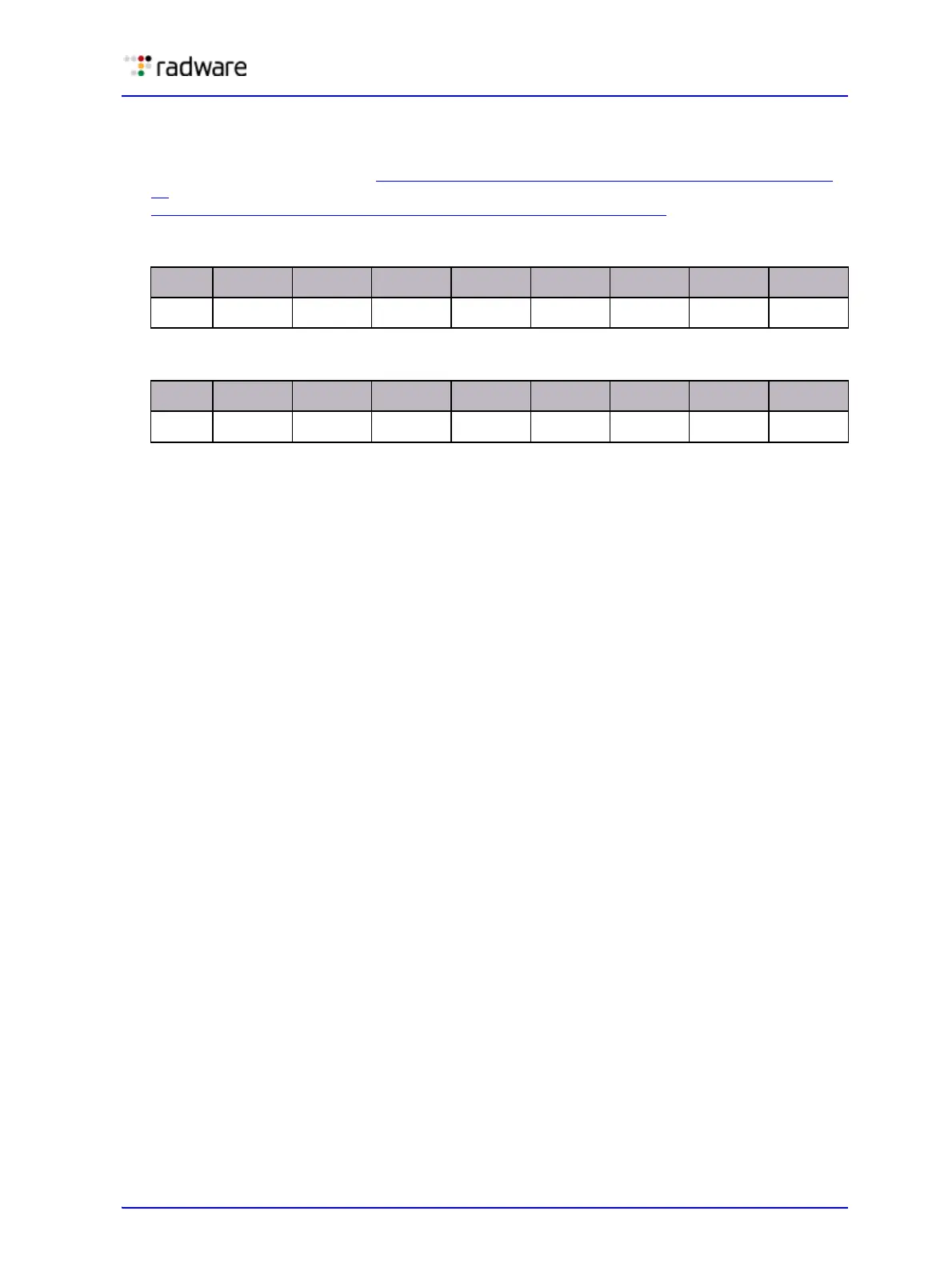
Table 9: Port-to-Core Usage with In-Band Management
Port 1 2 3 4 5 6/MNG1 7 8
Core
23123121
Table 10: Port-to-Core Usage with Out-of-Band Management
Port 1 2 3 4 5 6/MNG1 7 8
Core
23123
4/MP
i
i – Management Processor
21
 Loading...