EasyManuals Logo
Home>Raisecom>Remote Control>ISCOM RAX711

Raisecom ISCOM RAX711 User Manual

Raisecom ISCOM RAX711
67 pages
To Next Page IconTo Next Page
To Previous Page IconTo Previous Page
Page #21 background imageLoading...
Page #21 background image
Raisecom
ISCOM RAX711 (B)Product Description
Raisecom Technology Co., Ltd.
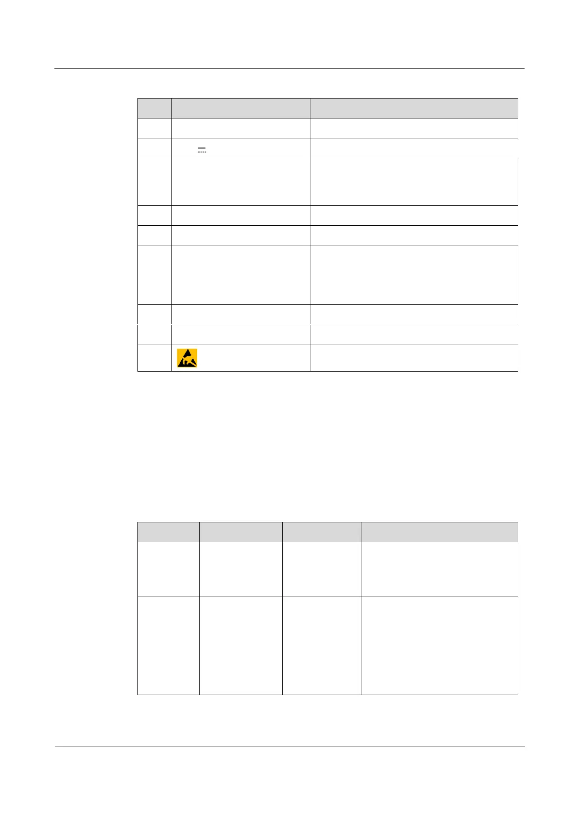
11
Table 3-1 Prints
No.
Print
Description
1
-100-200V
AC power interface
2
-48V
DC power interface
3
PWR2, PWR1, SYS, MGT
Power LED 2
Power LED 1
System working status LED
Fast deployment LED
4
CONSOLE
Console interface (RJ45)
5
SNMP, 100M, and LNK/ACT
SNMP interface (RJ45)
6
IN, OUT, CLK, and LOS(only
for ISCOM RAX711-CLK)
Ingress interface for clock synchronization
signal
Egress interface for clock synchronization
signal
Clock synchronization LOS LED
7
1000M, LNK/ACT, and NNI
Service uplink interfaces (SFP)
8
1000M, LNK/ACT, and UNI
Service downlink interfaces (Combo)
9
ESD sensitive symbol
3.2 Interfaces
3.2.1 Service interfaces
Table 3-2 lists types and usage of service interfaces on the ISCOM RAX711(-CLK).
Table 3-2 Service interfaces
Interface
Name
Type
Description
0/10/2
Service uplink
interface
SFP
The interface supports the
following optical modules:
1000BASE-X
100BASE-FX
1/11/4
Service downlink
interface
Combo optical
interface (SFP)
The interface supports the
following optical modules:
1000BASE-X
100BASE-FX
The interface supports the
following electrical modules:
10/100/1000BASE-T

Table of Contents

Questions and Answers:

Question and Answer IconNeed help?

Do you have a question about the Raisecom ISCOM RAX711 and is the answer not in the manual?

Raisecom ISCOM RAX711 Specifications

General IconGeneral
BrandRaisecom
ModelISCOM RAX711
CategoryRemote Control
LanguageEnglish