Raisecom
ISCOM2600G (A) Series Product Description
Raisecom Proprietary and Confidential
Copyright © Raisecom Technology Co., Ltd.
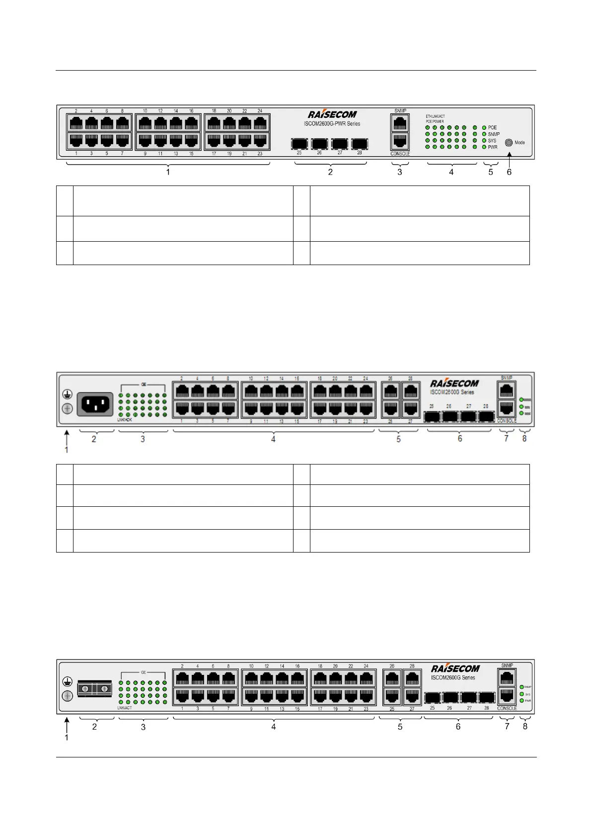
Figure 3-5 Front panel of ISCOM2624G-4C-PWR-AC/DC
Service downlink interfaces (1–24)
Service uplink SFP optical interfaces (25–28)
SNMP interface and Console interface
POE, SNMP, SYS, and PWR LEDs
Mode button (PoE mode switching)
ISCOM2624G-4GE-AC
Figure 3-6 shows the front panel of the ISCOM2624G-4GE-AC.
Figure 3-6 Front panel of ISCOM2624G-4GE-AC
Service interfaces (1–28) LEDs
Service downlink interfaces (1–24)
Service uplink GE interfaces (25–28)
Service uplink SFP optical interfaces (25–28)
SNMP interface and Console interface
ISCOM2624G-4GE-DC
Figure 3-7 shows the front panel of the ISCOM2624G-4GE-DC.
Figure 3-7 Front panel of ISCOM2624G-4GE-DC