R&S SM300 Instrument Assembly for Board and Module Exchange
Version 04 37
Service Manual SM300: 1147.1652.00 Instrument Part No SM300: 1147.1498.03
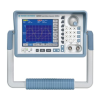
1.3.3.2 Handle
Removing
Remove front protector (see section 1.3.3.1).
Open lateral tension lever on handle. Pull handle out towards the front
using both hands.
Figure 1-3
Caution
Handle can jam in the slot if pressure is applied on only one side!
Installing
1. Open lateral tension lever on handle. With both hands on front side of
handle, push it into lateral slots (see
Figure 1-3).
2. Position handle as desired and close tension lever.
3. Install front protector. (see section
1.3.3.1).
1.3.3.3 Case Top and Bottom and Rear Frame with 2 Rear Bars
Removing the rear
frame
1. Remove both protectors (see section 1.3.3.1).
2. Remove handle (see section
1.3.3.2).
3. Undo 12 screws on rear. (see
Figure 1-5) .
4. Undo two upper and two lower screws.
5. Pull off frame with rear bars toward rear.(see
Figure 1-6) (Rear bars are
held in place in frame by means of frictional connection).
Removing the case
top and bottom
1. Undo 12 side screws. (see
Figure 1-4).
2. Undo upper and lower screws (one each).
3. Remove cases. (see
Figure 1-7).
Note
Please note that spare part 1147.1381.00 is shipped with 3 rear bars. For
the SM300 only 2 are needed.

 Loading...