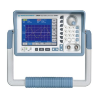
R&S SM300 Instrument Assembly for Board and Module Exchange
Version 04 43
Service Manual SM300: 1147.1652.00 Instrument Part No SM300: 1147.1498.03
1.3.3.9 Aircase Unit with Display and Fan
Removing aircase
unit
1. Remove both protectors (see section 1.3.3.1).
2. Remove handle (see section
1.3.3.2).
3. Remove rear frame and both cases (see section
1.3.3.3).
4. Remove carrier lid (see section
1.3.3.5).
5. Remove front unit (see section
1.3.3.7).
6. Remove duoblind (see section
1.3.3.8).
7. Remove generator module (see section
1.3.3.11).
8. Undo 5 special screws on side (see
Figure 1-22) and lower 2 special
screws (see
Figure 1-23).
9. Undo 2 countersunk screws (see
Figure 1-24) located below the
backplane.
10. Route spinwheel and keyboard cables through opening and disconnect
from backplane. Disconnect display cable and fan cable latch from
backplane.
11. Pull aircase unit off toward front (see
Figure 1-25).
Caution
Make sure the color marking of spinwheel cable is at top and the color
marking of keyboard cable points towards the display plug!
Installing aircase
unit
1. Mount aircase unit on instrument from front.
2. Connect display cable and fan cable latch to backplane.
3. Route spinwheel and keyboard cables through opening and plug into
backplane.
4. Press aircase unit onto carrier unit and fasten it in place with 5 special
screws on side and 2 special screws at bottom (similar to
DIN 7985 M3×5).
5. Fasten two countersunk screws located below backplane (DIN 96
M2.5×6).
6. Install generator module (see section
1.3.3.11).
7. Install duoblind (see section
1.3.3.8).
8. Install front unit (see section
1.3.3.7).
9. Install carrier lid (see section
1.3.3.5).
10. Install both cases and rear frame (see section
1.3.3.3).
11. Install handle (see section
1.3.3.2).
12. Install both protectors (see section
1.3.3.1).
Figure 1-22 Figure 1-23

 Loading...